This is a guide to creating realistic ball physics using Basic Motion Device Component.
This guide focuses on implementing horizontal ball physics - perfect for stages where the ball stays on the ground, moves toward a goal, and resets if it misses the mark.

1. Initial Setup
There are currently two primary methods for creating realistic ball physics in your stage: the Projectile Motion Device Component and the Basic Motion Device Component. This guide focuses on the Basic Motion Device for grounded movement.
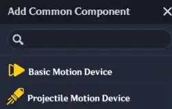
Motion Device Components
Creating the Object
- Select your model: Choose the "Stone Ball" from the Dynamic Unit list, or create a custom ball using a decorations in the object properties.
- Save object as prefab
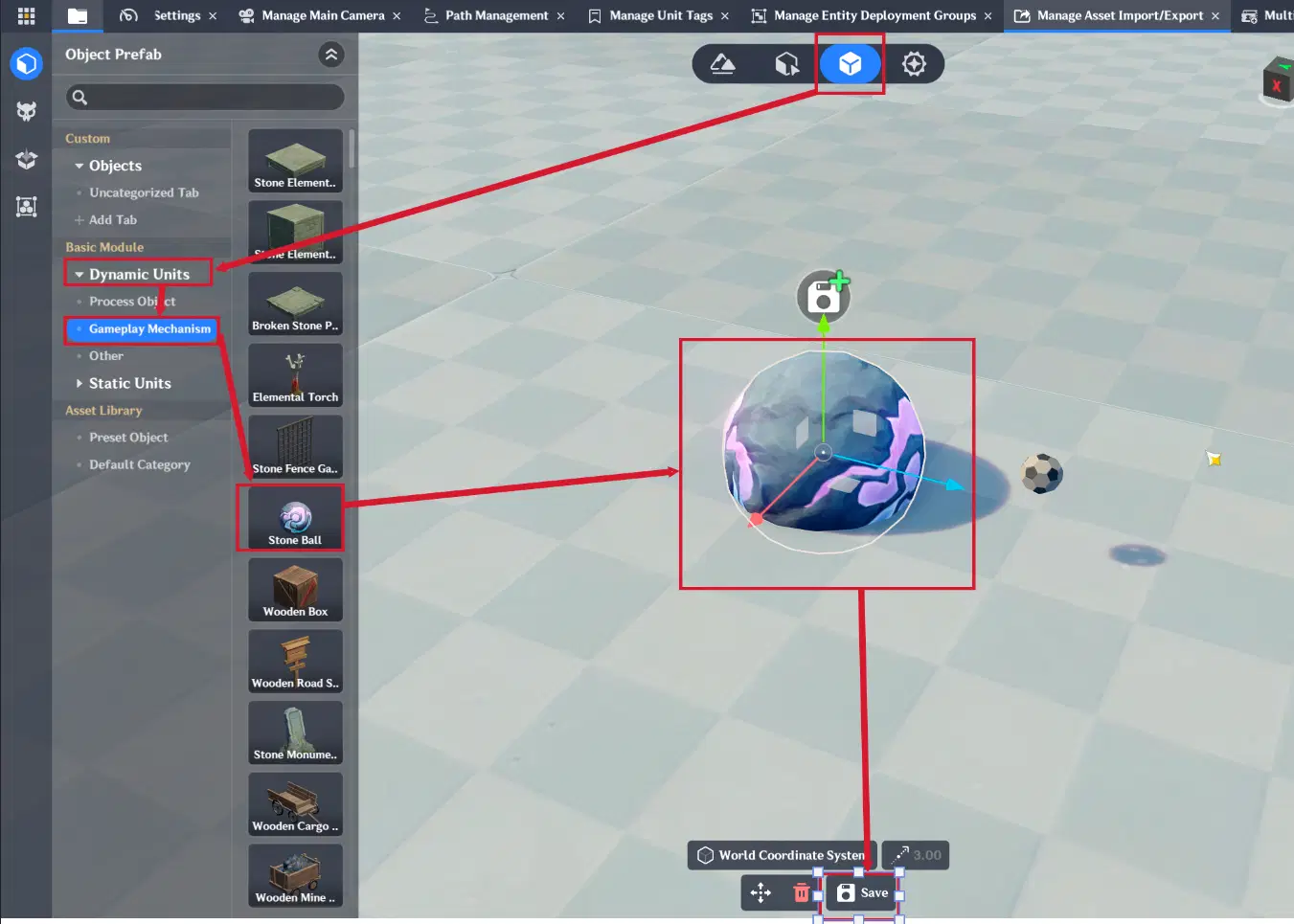
Object creation
3. Add the Component: Navigate to the Common Component tab and add the Basic Motion Device.
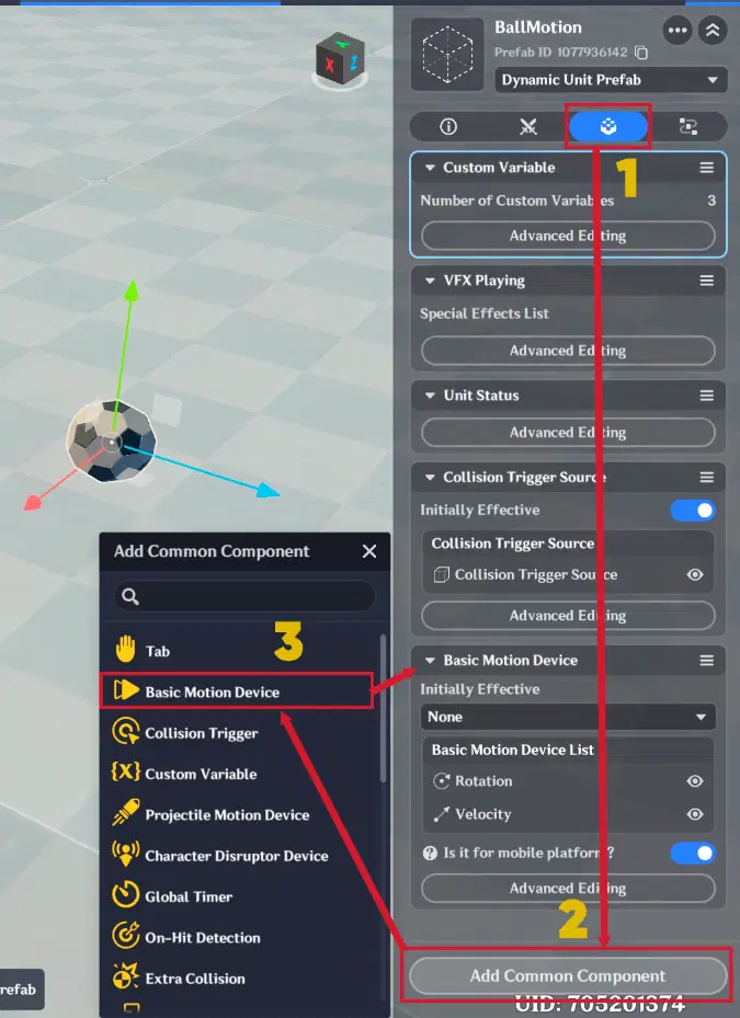
Basic Motion Device Component
Advanced Editing
To ensure the ball moves and rolls realistically, open Advanced Editing and create two separate motion devices:
- Uniform Linear Motion: Controls the ball's movement across the stage.
- Uniform Rotational Motion: Controls the ball's visual rotation (rolling effect).
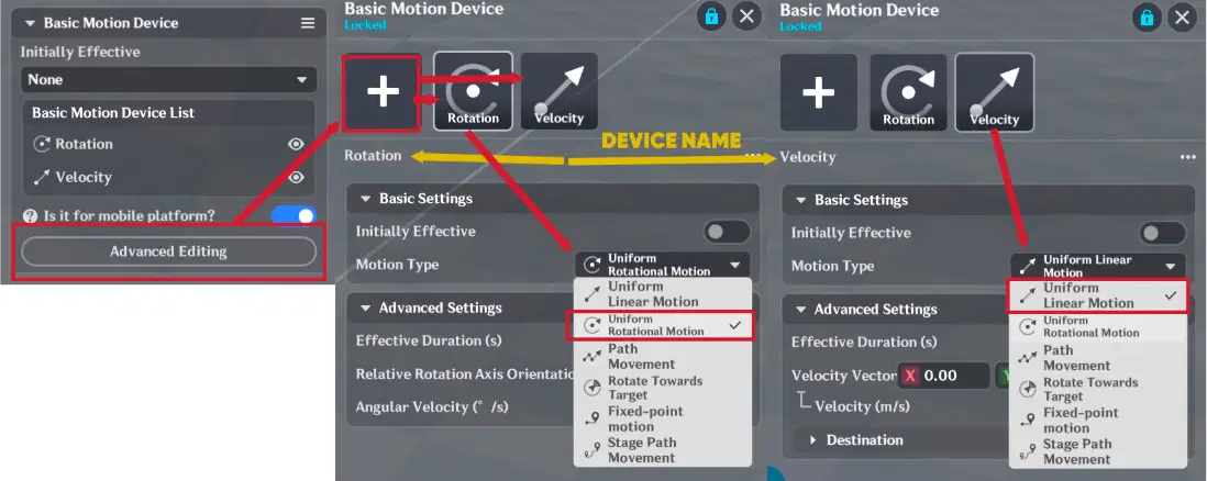
Basic Motion Devices

1.1. Uniform Linear Motion configuration
The settings are as follows:
- Initially Effective: Off
- This ensures the motion only triggers when activated by a node graph, rather than starting immediately upon spawn.
- Effective Duration: 1 second
- While you can adjust this, we will be dynamically updating this value every 0.03 seconds via logic, so a small initial duration is ideal.
- Velocity Vector (x, y, z): Defines the ball's travel direction.
- X: Left / Right
- Y: Up / Down
- Z: Forward / Backward
- To move the ball forward, set the Z value. In this case, 30 m/s is enough.
Note: High speeds can cause the ball to skip over collision boundaries. At high speeds you will need to create multiple collision triggers to properly handle the events associated with them.
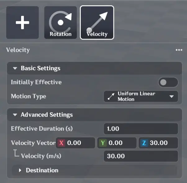
Uniform Linear Motion configuration
1.2. Uniform Rotational Motion configuration
The settings are as follows:
Initially Effective: Off
- Prevents the ball from rotating before it is kicked.
Effective Duration: 1 second
- Similar to the linear motion, this will be dynamically updated every 0.03 seconds via logic.
Relative Rotation Axis Orientation (x, y, z): Defines the axis of rotation.
- X:1, Y:0, Z:0 → Forward/Backward roll
- X:0, Y:1, Z:0 → Spinning (like a top)
- X:0, Y:0, Z:1 → Sideways tilt/roll
- In this case we will set this to (1, 0, 0) for a standard forward roll.
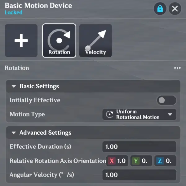
Uniform Rotational Motion
Custom Variables
Finally, we will create the following Custom Variables within the ball object to handle physics calculations:
- Velocity: (Type: 3D Vector) – Used to dynamically track and update the ball's movement vector.
- canBounce: (Type: Boolean) – A toggle needed for collision and bounce logic in later steps.
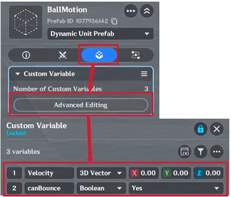
Custom variable creation
2. Kick logic
The next step is implementing the kicking mechanic. To make the aim intuitive for players, we use a Ball Dummy - a non-physical replica of the ball model to visualize the kick direction before the actual ball is launched.
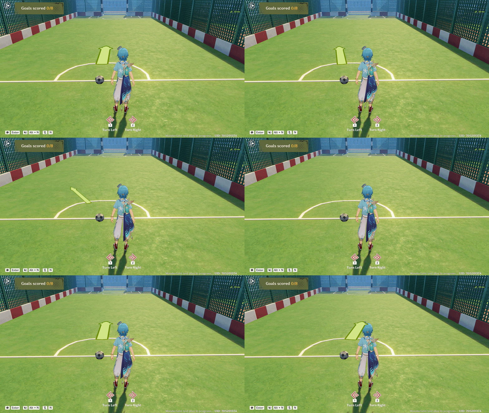
Ball launch direction visualization
2.1. Ball Rotation Visualization
To help players aim, use a VFX Playing Component to display the kick direction.
VFX configurations are following:
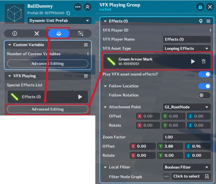
VFX configuration
Interactive Controls
To allow players to rotate the ball and adjust the aim, create two custom buttons in the UI Control Group Management (Key Type: Interactive Event).
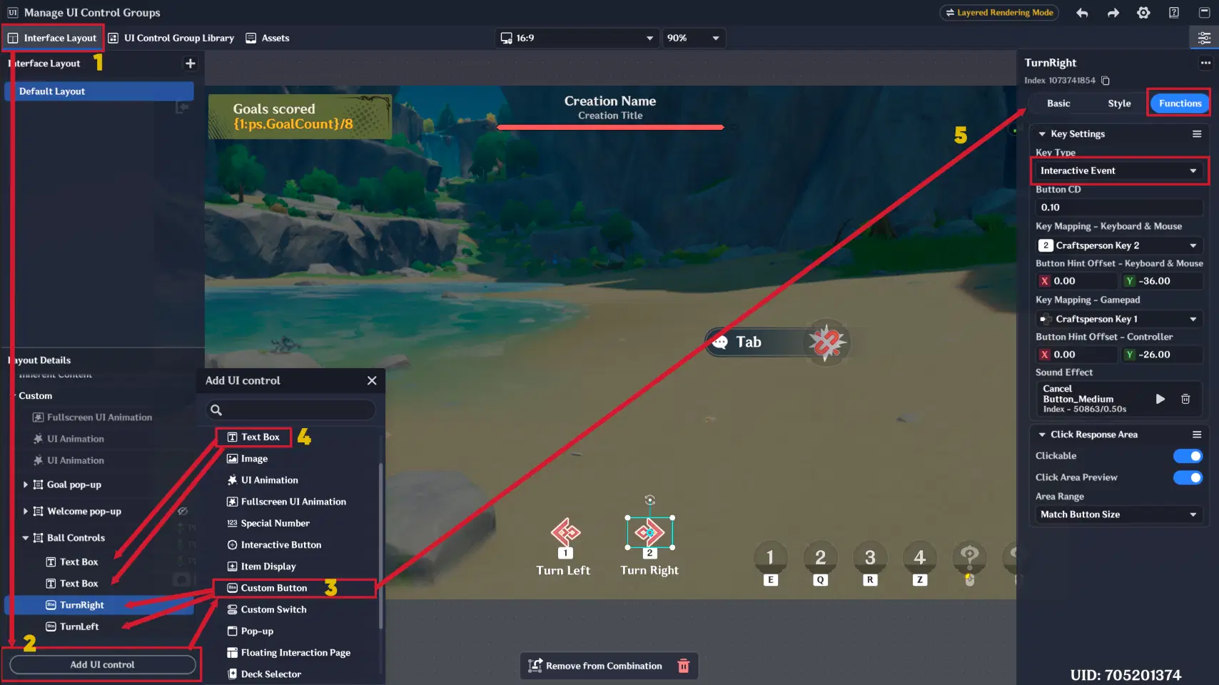
Custom Button creation
Node Graph Logic (Attached to Player Entity)
When a button is pressed, the logic should follow these steps:
- Update Rotation: Adjust the Rotation custom variable by a step of 10 (only the Y-component should change).
- Refresh Entity: Remove the current ball dummy and spawn a new one with the updated rotation.
- Variable Tracking: Store the new ball entity in the Player’s "Ball" custom variable (this is essential for deleting or replacing the entity later).
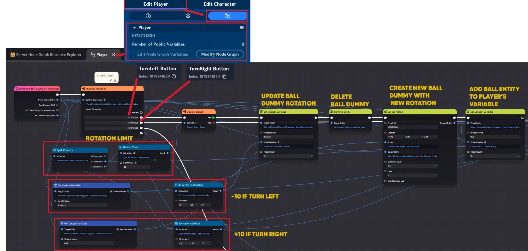
Node Graph logic
Activation
Add a Tab Component to the ball dummy. When the player selects tab, it will trigger the actual ball creation and initiate movement logic.
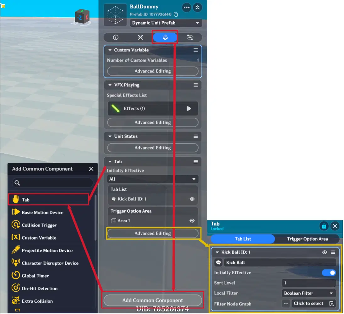
Ball dummy Tab component
2.2. Ball movement Physics
Once the ball is created, the node graph calculate a Velocity Vector based on the dummy’s rotation. To convert the rotation angle into movement coordinates, use the following formulas:
- X = sin(rotation angle)×30
- Y = 0 (In this case we don't use Y movement, ensures the ball stays grounded)
- Z = cos(rotation angle)×30
(Note: 30 represents the initial Z-component speed; adjust this value to change the kick power if needed)
Angle Conversion
In Miliastra Wonderland, the Sine Function and Cosine Function nodes require inputs in radians. To convert your degrees to radians, multiply the rotation angle by 0.01745.
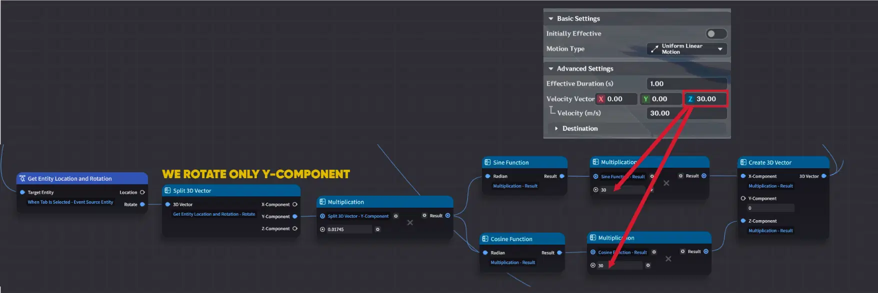
Velocity Vector calculation
Activating Motion Devices
- Uniform Linear Motion:
- Apply the newly calculated X, Y, Z vector.
- Save this vector into the ball's "Velocity" custom variable for future physics updates.
- Activate the new Uniform Linear Motion Device.
- Uniform Rotational Motion:
- Angular Velocity: Multiply the Velocity Vector’s Z-component by 25 (increase this multiplier for a faster visual spin).
- Rotation Axis Orientation: Set to (1, 0, 0) to ensure the ball rolls forward relative to its movement.
- Activate the new Uniform Rotational Motion Device.
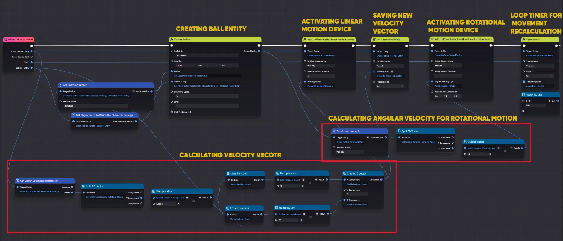
Ball movement logic
2.3. Physics Loop
To simulate realistic friction and deceleration, we implement a logic loop that continuously updates the ball's state.
The Friction Logic
Start a Loop Timer set to trigger every 0.03 seconds. During each tick, the node graph performs the following:
- Velocity Decay: Multiply the current Velocity vector by 0.95 (the speed loss coefficient). This gradually slows the ball down.
- Update Motion: Apply this updated vector to the Uniform Linear Motion Device to reflect the new, slower speed.
Stopping & Cleanup
To prevent the ball from rolling infinitely at microscopic speeds, add a Branch Node to check if the ball has effectively stopped:
- Condition: Check if the Absolute Value of both the X and Z velocity components is ≤ 0.5.
- Action: If the condition is met, the ball is considered "stopped." Destroy the ball entity to allow a new ball to be kicked from the starting position.
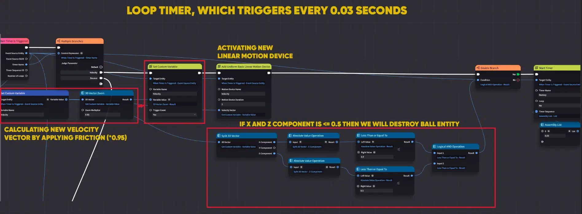
Ball's friction and deceleration logic
Tip: You can adjust the 0.95 coefficient to change the surface friction. A lower value (e.g., 0.90) will make the ball stop faster, simulating grass, while a higher value (e.g., 0.98) will make it slide longer, like ice.
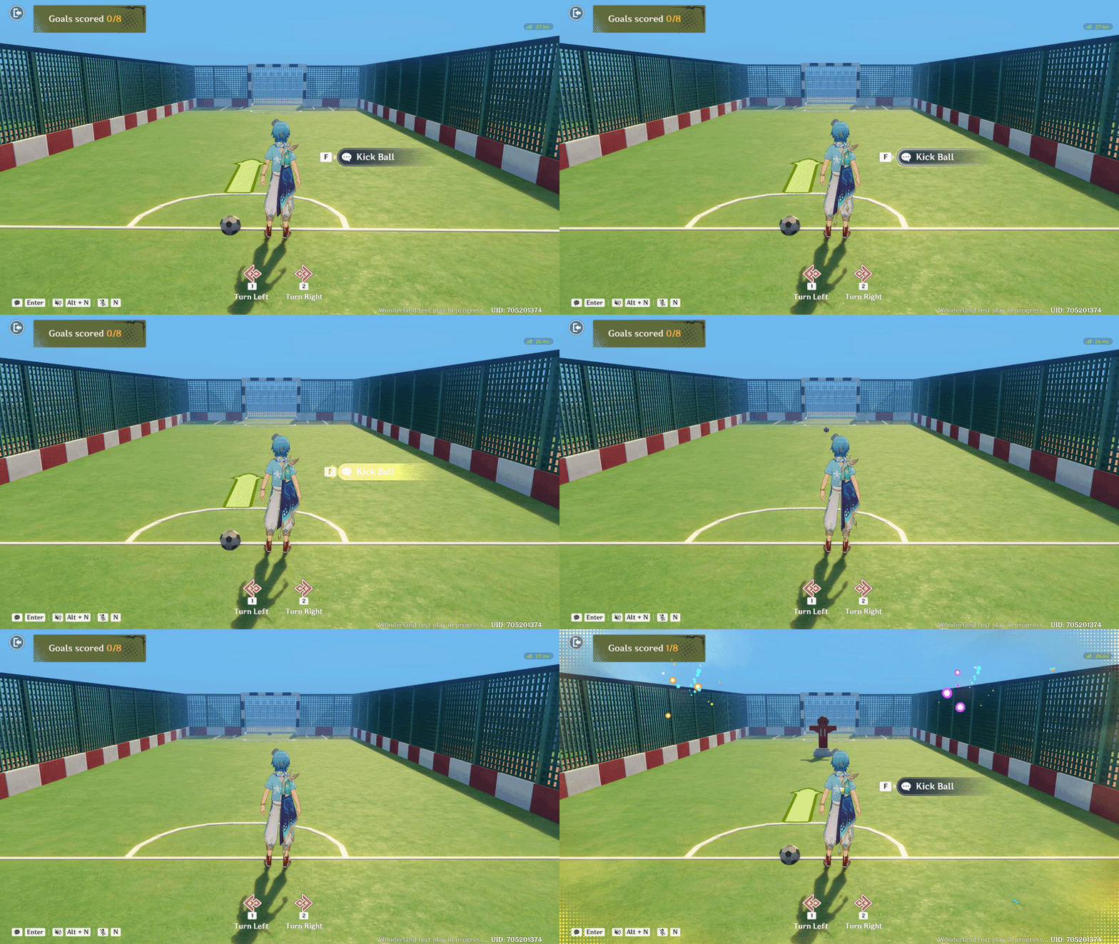
Ball physics showcase
3. Wall collisions
To make the ball interact with the environment, you must set up a collision trigger system. Obstacles and walls should be Dynamic Units with a Collision Trigger Component, while the ball must have a Collision Trigger Source Component to interact with them.
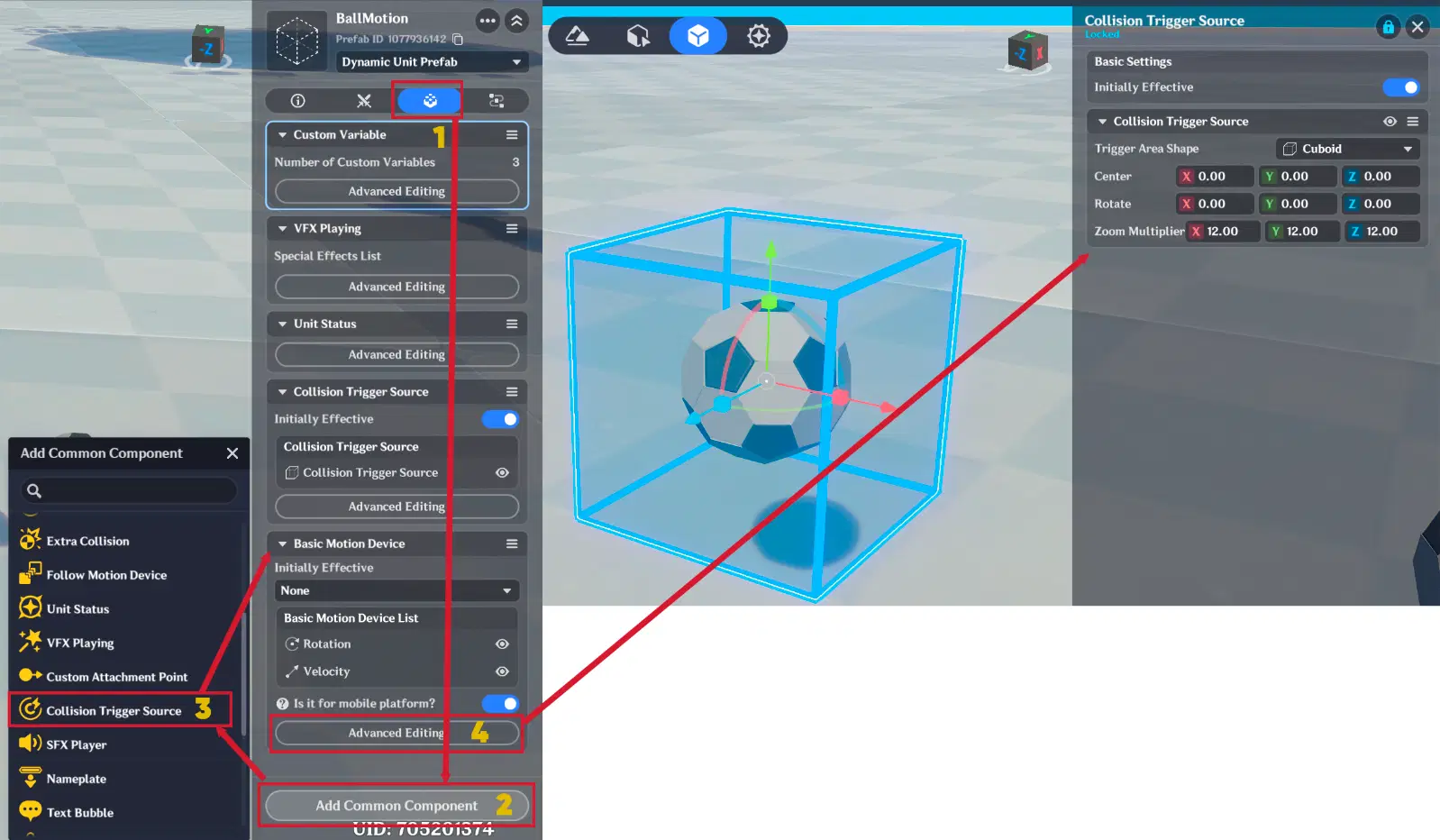
Ball Collision Trigger Source
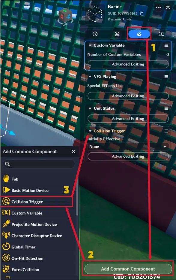
Barier Collision Trigger
Tip: Set the Ball’s Collision Trigger Source slightly larger than the model itself to ensure more consistent detection.
High-Speed Detection (Dual Triggers)
Because the initial velocity (30m/s) is high, a single trigger might fail to correctly detect the ball at different speed. To solve this, use two triggers for each wall:
- Outer Trigger: Positioned further from the wall to catch the ball when it exceeds 20m/s.
- Inner Trigger: Positioned near the wall surface for speeds between 0–20m/s.
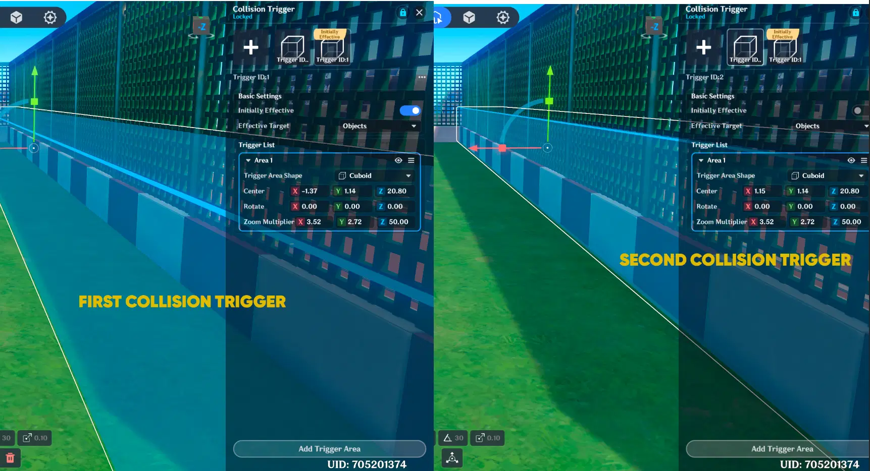
Barier's collision triggers
To manage these, use the "BounceCount" custom variable to switch between them. Once the first bounce occurs, deactivate the outer trigger and enable the inner one to maintain precision as the ball slows down.
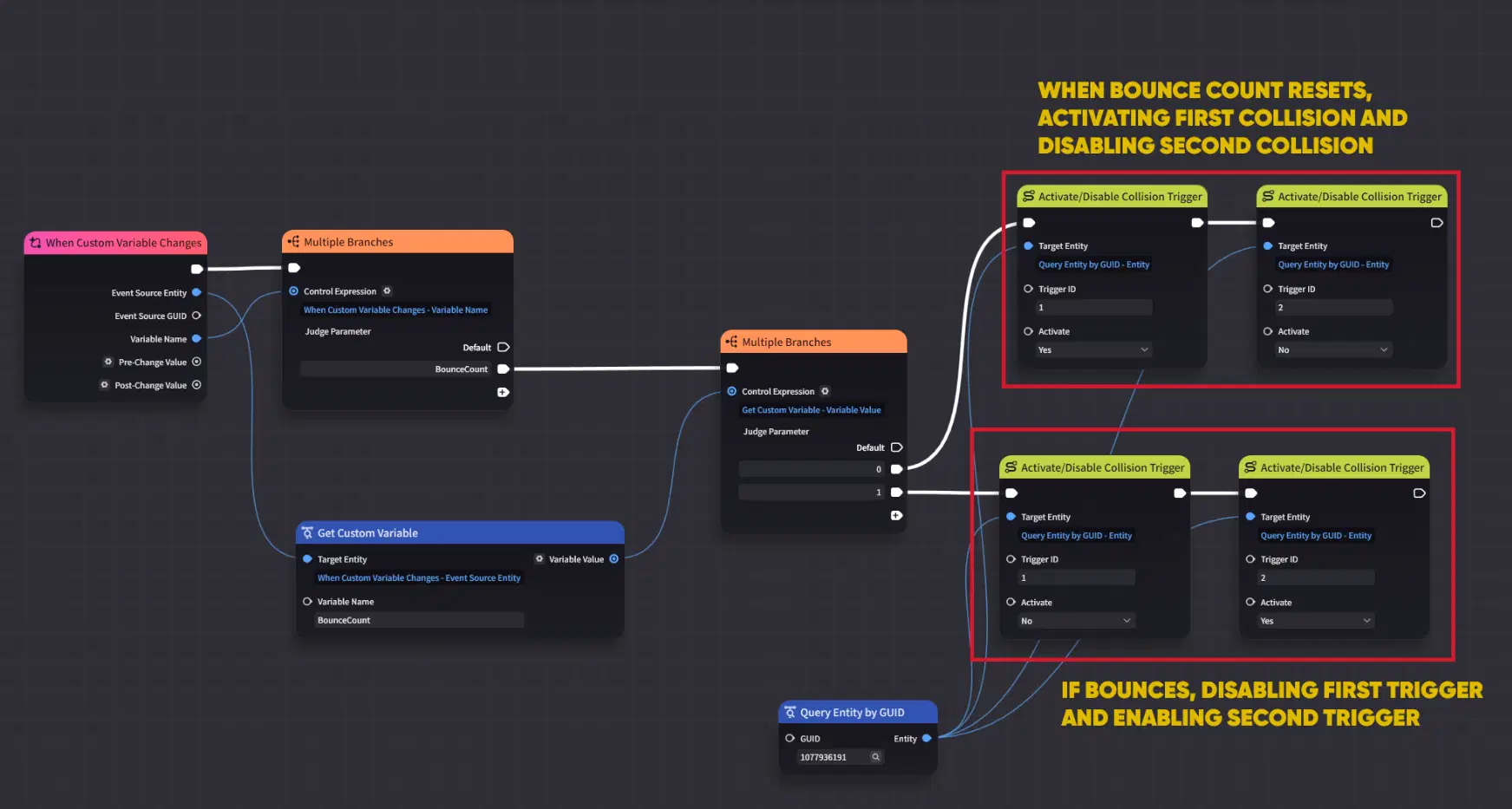
Bounce Count processing
Bounce Logic & Anti-Stuck Measures
To prevent the ball from triggering multiple collisions at once and getting "stuck" inside a wall, use the canBounce boolean variable:
- On Collision: Check if canBounce is True.
- Locking: Immediately set canBounce to False upon impact.
- Cooldown: Use a 1-second delay before setting it back to True, allowing the ball to clear the collision zone.
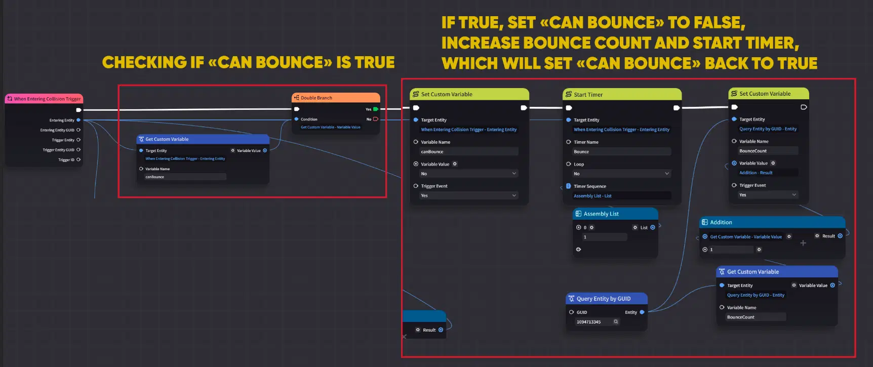
CanBounce variable processing
Note: It is recommended to create two "canBounce" separate variables. Since the 1-second cooldown may not finish before the ball hits a different type of wall, using two variables ensures that different collision types will trigger correctly in time.
Calculating the Rebound
When the ball hits a surface, you must invert the velocity and apply Rebound Damping (speed loss upon impact) by multiplying the vector by 0.8.
For Horizontal Walls: Invert the X-component of the velocity vector (e.g., X=−X).
For Vertical Walls: Invert the Z-component of the velocity vector (e.g., Z=−Z).
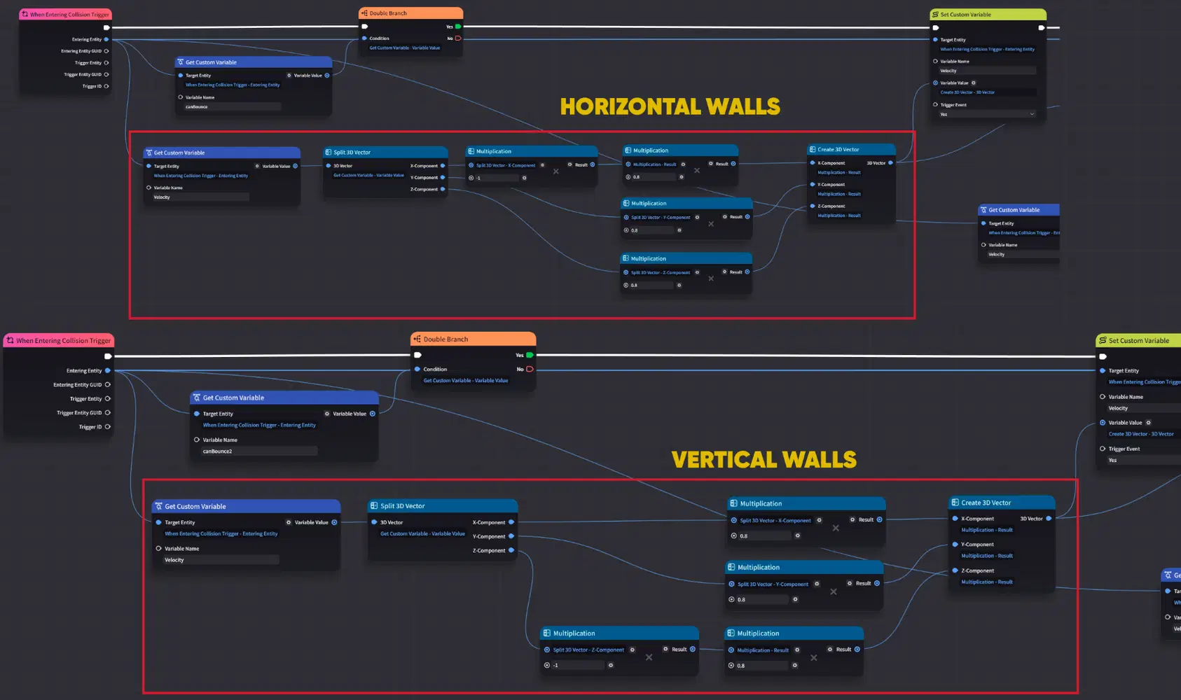
Rebound damping calculation
Applying the Change
After calculating the new reflected vector:
- Update the Velocity custom variable.
- Re-activate the Uniform Linear Motion and Uniform Rotational Motion devices with the new values to change the ball's direction.
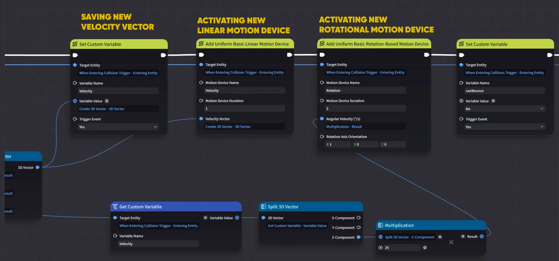
logic for applying changes
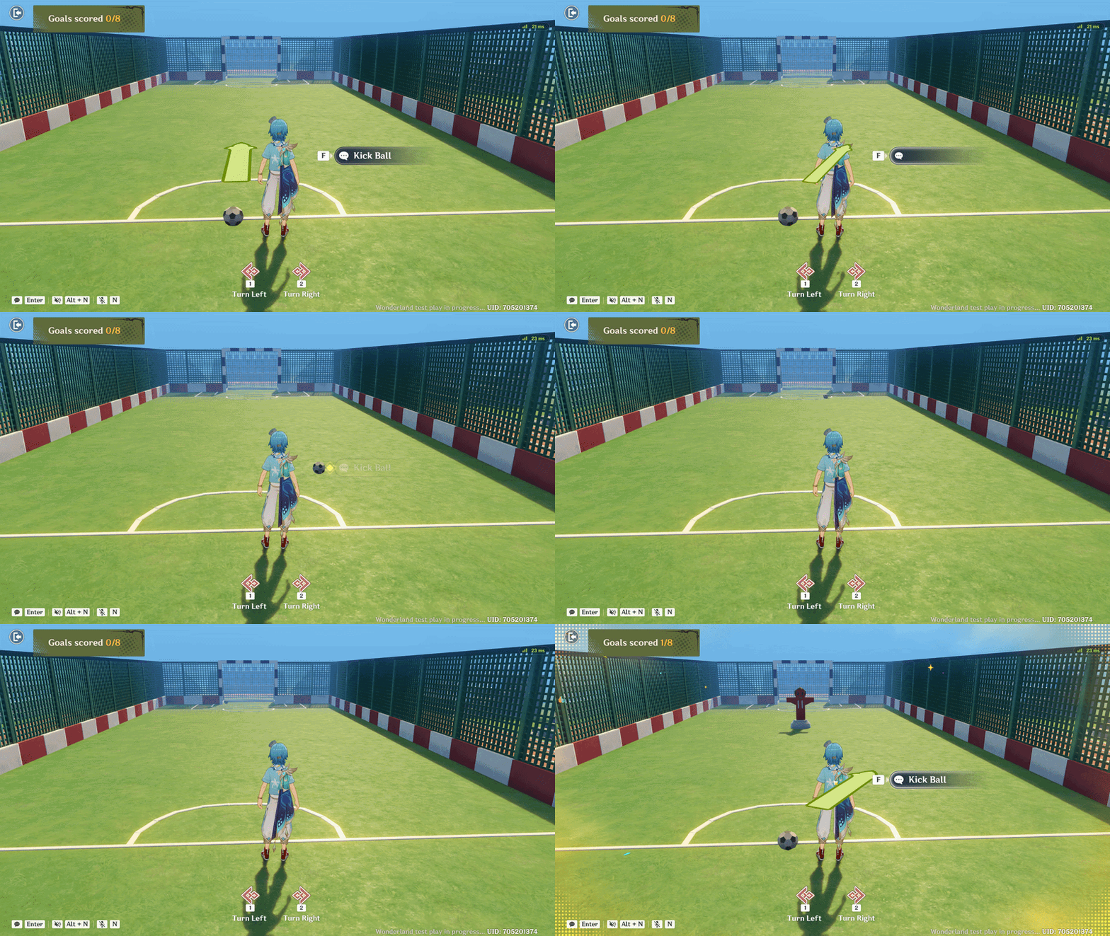
Ball bounce showcase
I hope this guide helps you better understand how to create ball physics and implement them in your stages.