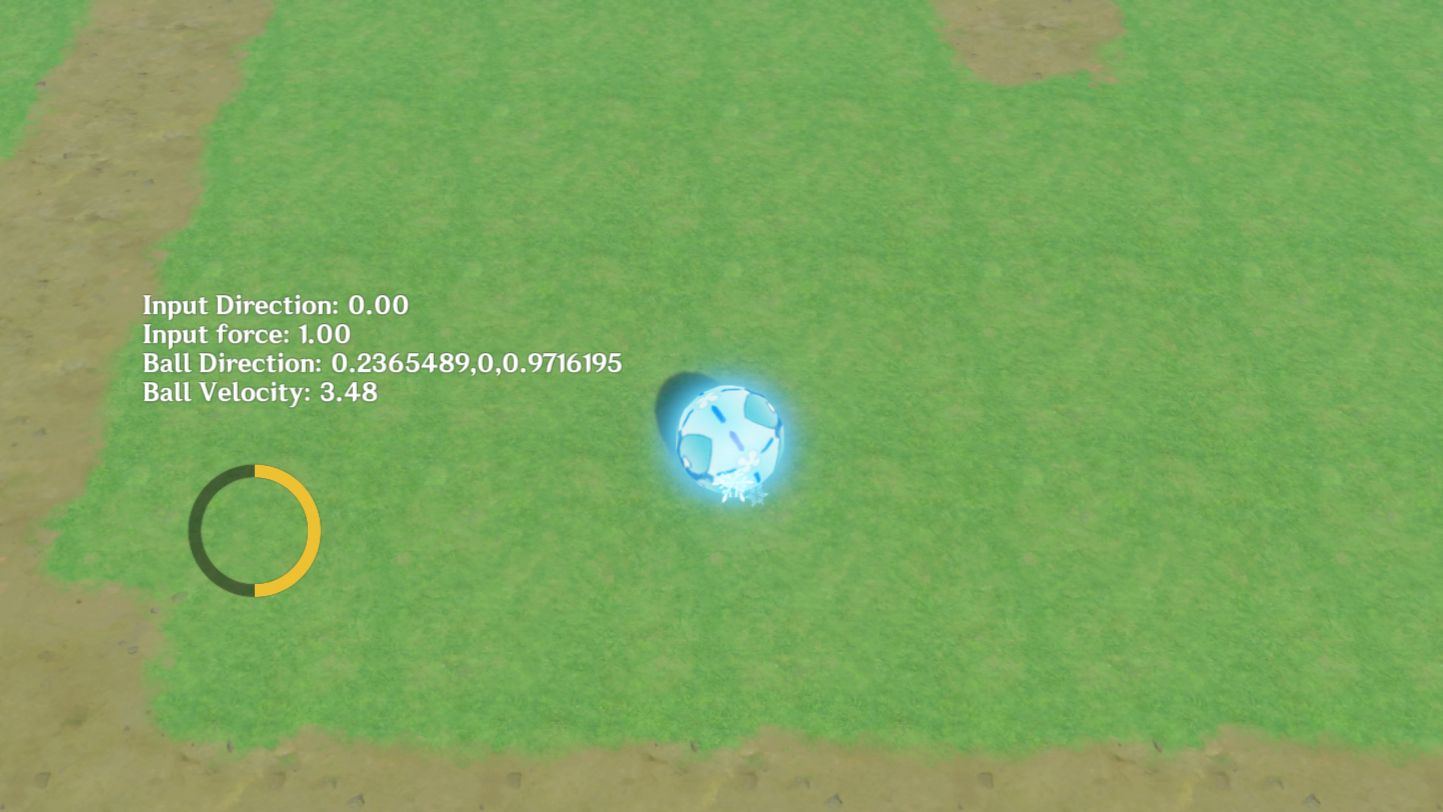
This post introduces how to use WASD to control objects for inertial movement with acceleration and deceleration in Miliastra Wonderland.
The complete save file is now available in the Resource Center :https://act.hoyoverse.com/ys/prod/ugc/component-store/index.html#/item/2051487126746329088 to download and use it!
1. Principle & Overview
By using a server-side timer as a tick signal, treating each tick as a frame update, and accumulating the motion action amount onto the moving body each frame to refresh the motion device, we achieve acceleration and deceleration control that aligns with physical intuition.
To capture client input, a looping status triggers an instant skill, which retrieves the player's input and sends a signal.
Related Knowledge Involved
- Basic usage of object camera
- Timer-triggered skills within statuses and the corresponding client-side invocations
- Basic motion device usage and optimization techniques
- Implementing updates with timers
- 3D vector calculations — a bit of linear algebra knowledge
- Converting directional input into a 3D vector using the Bhaskara approximation formula
Next, we'll break down the entire workflow into several modules:
- Capturing Client Controls
- Modifying the camera
- Implementing basic deceleration-based motion
- Intervening in motion via input
Finally, we'll achieve a complete motion control system. Let's get started!
2. Reading Player Movement
In version Luna VI, two key features were introduced: triggered skills on the timer and client nodes for capturing user input. These are the prerequisites that make this functionality possible.
Prior to this, most attempts at simulating WASD control relied on impulse + collision methods, but the sensitivity and accuracy were far from ideal.
2.1 Approach
- Create an instant skill and add a node graph to capture the player's input at the current moment. Add this skill to the class as a custom skill.
- Add a new status with an infinite duration. Configure this status with a timer-triggered skill effect, selecting the custom skill you just created.
- Add this status as the unit status for the class, so the client will invoke it continuously.
2.2 Hands-On Implementation
2.2.1 create a skill
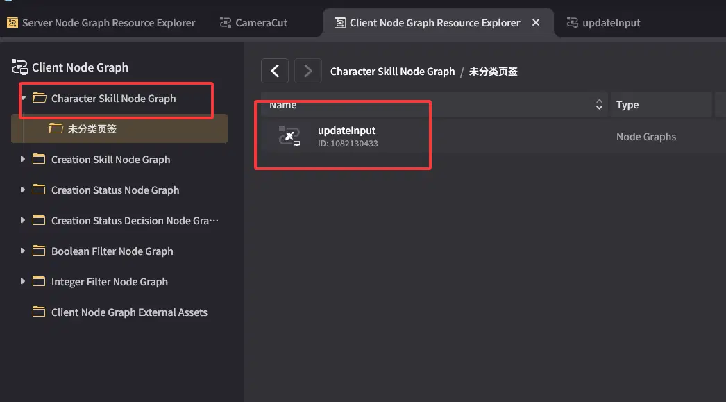
First, in the client-side nodes, add a skill node graph for [Update Input].
Now let's create a skill. Note that it should be an instant skill. Since we want to invoke it freely, do not set any targeting method or cooldown for it.
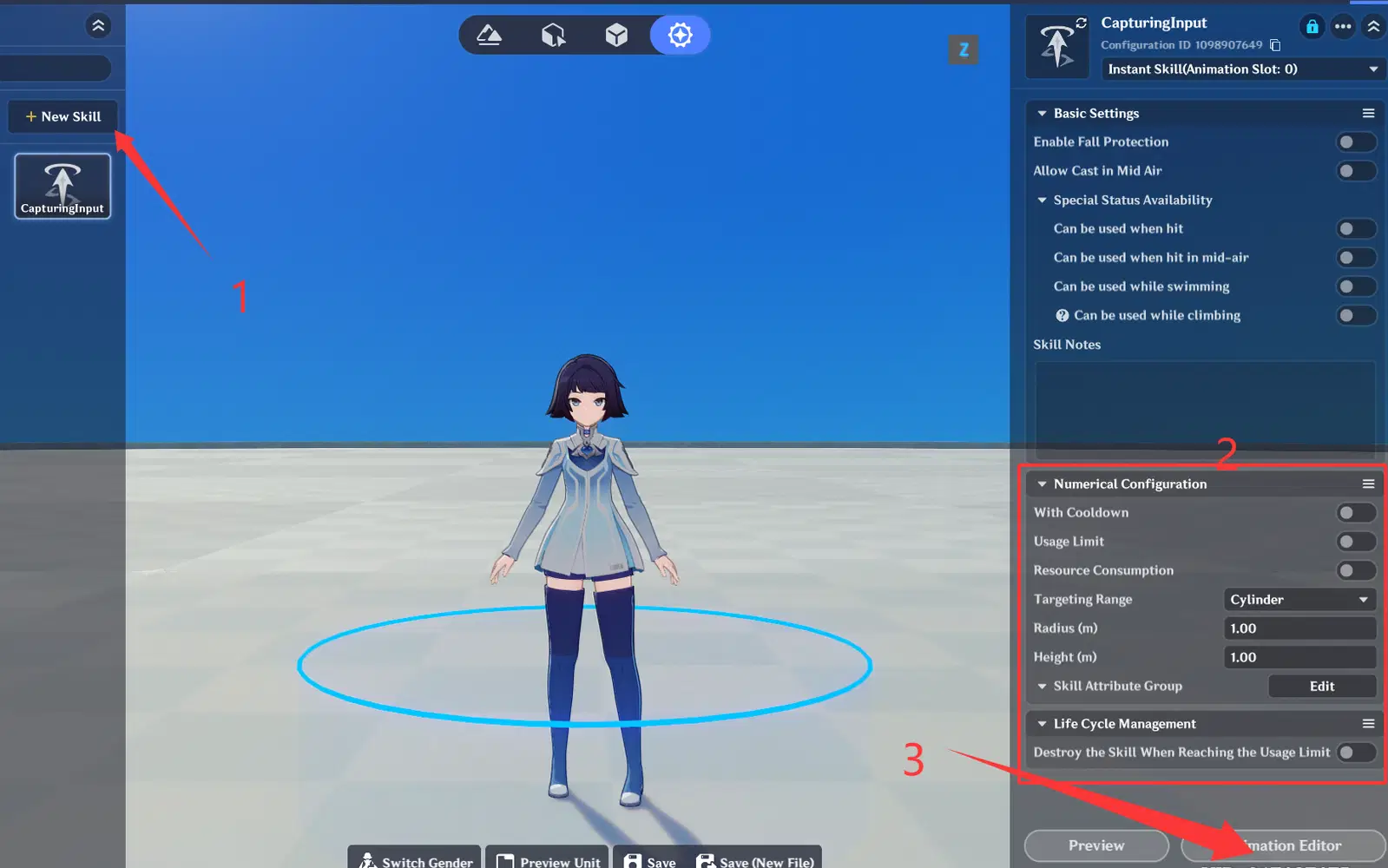
Next, add this node graph to the instant skill.
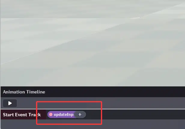
2.2.1 Create a status that triggers the skill
First, go to the class configuration. For the skill we just created, we need to bind it to a slot.
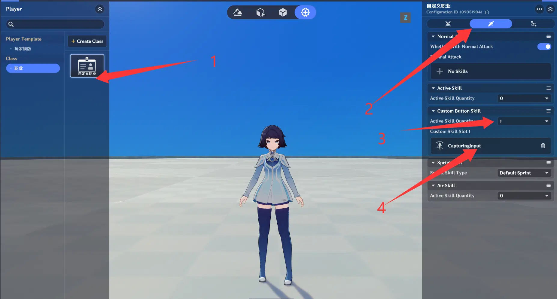
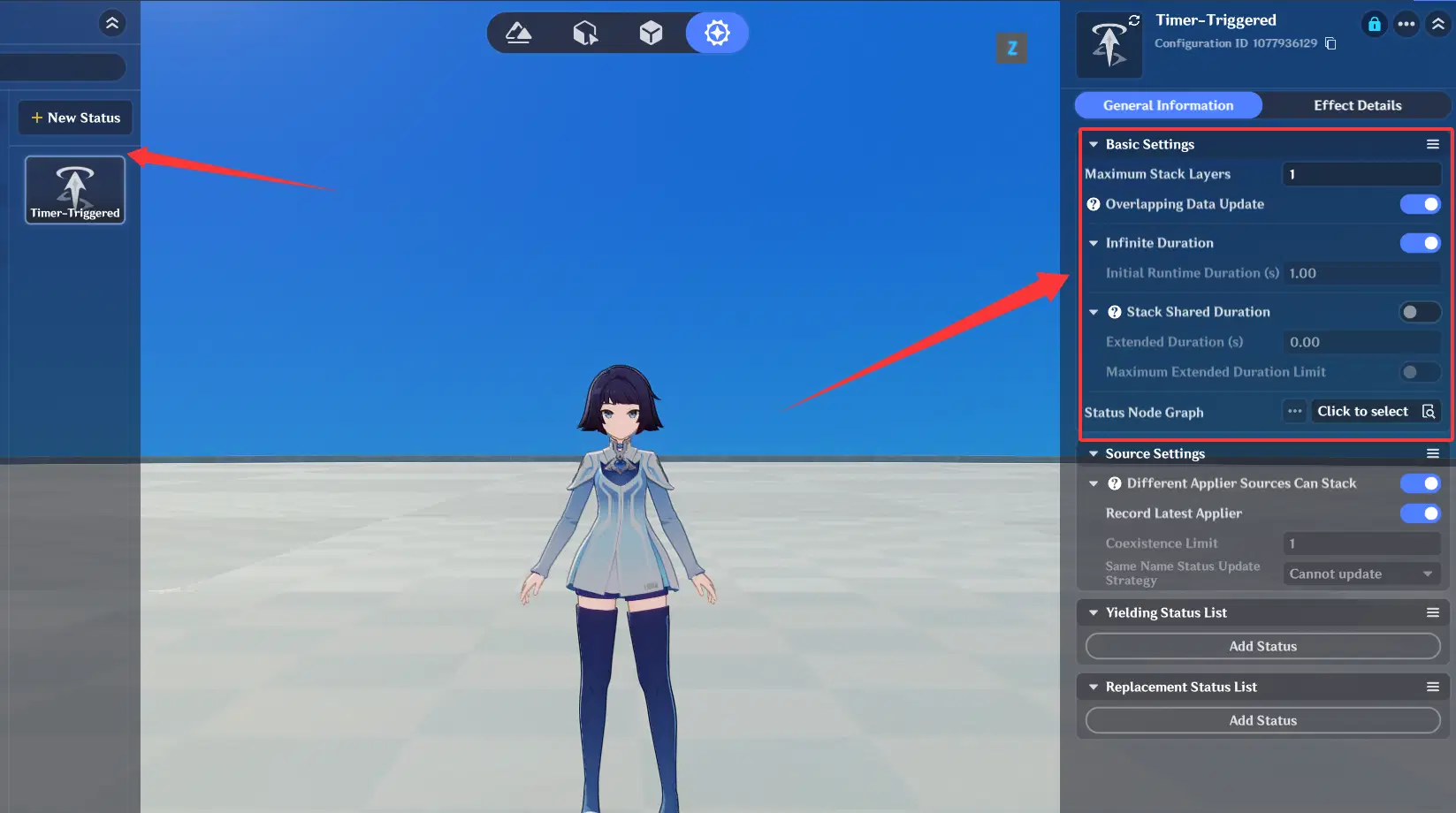
Next, create a status capable of triggering the skill. Note that this state must be permanently active (infinite duration).
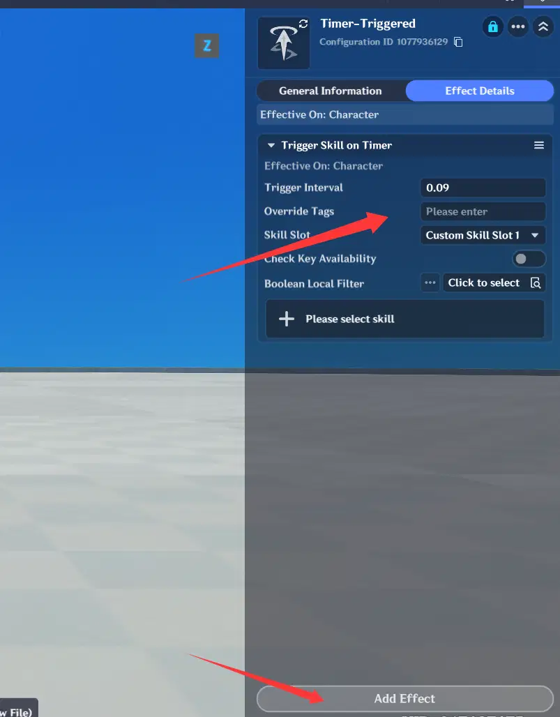
In the effects, add a timer-triggered skill release, and configure the corresponding timing and slot (the one we just set up).
The interval is set to 0.09 seconds because we plan to use a control frequency of 11.11 fps. This will be explained further in the movement implementation section later.
2.2.3 Add this status as the unit status for the class
In the class settings, add the status we just configured to the unit status.
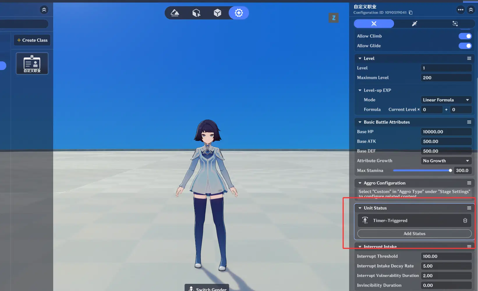
Next, when this wonderland is running, the status will continuously release the skill, and our updateInput node graph will be triggered at a high frequency as well.
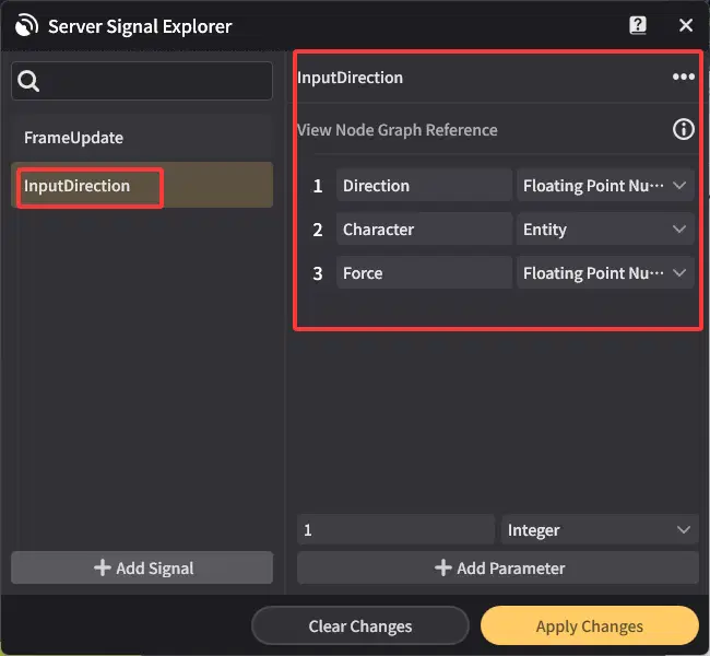
Now let's go back and modify the node graph we created earlier. First, open the server signal explorer.
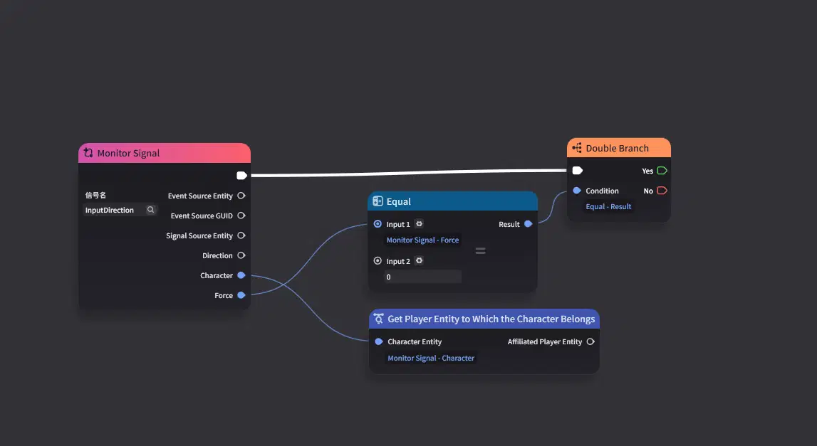
We need to set three parameters: Direction, Strength, and Character. These are the required parameters. If you don't need multiplayer functionality, the Character parameter can be left unset.
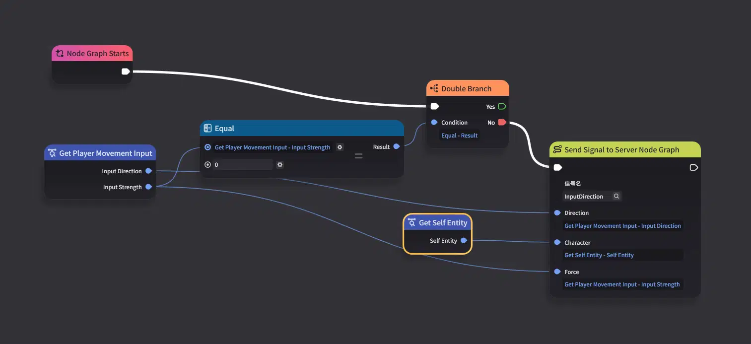
In the node graph, we need to add a check: whether the strength is greater than 0, and only then pass the input to the server. This helps reduce performance overhead.
3. Object Camera Binding
In this example, we don't need the player's perspective, so the camera should be switched to the sphere as soon as the player entity is created.
Since the sphere undergoes real-time rotational movement, we cannot bind the camera directly to it. Instead, we first create an empty model entity that follows the sphere's position. This solves the rotation issue.
Additionally, it's recommended to place the character somewhere out of sight — after all, we only need it to capture input, and the main focus is the moving object.
3.1 Add an object camera
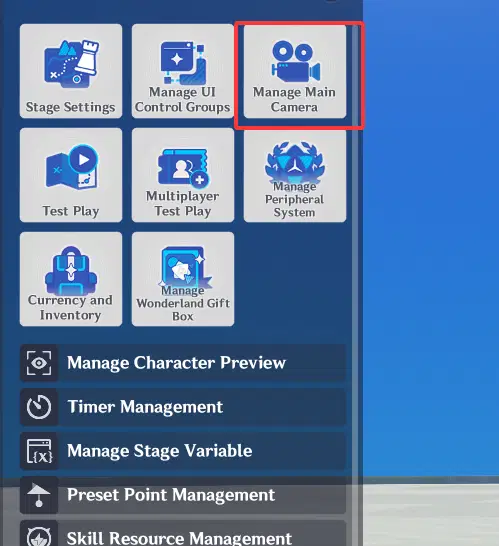
First, open the Camera Editor
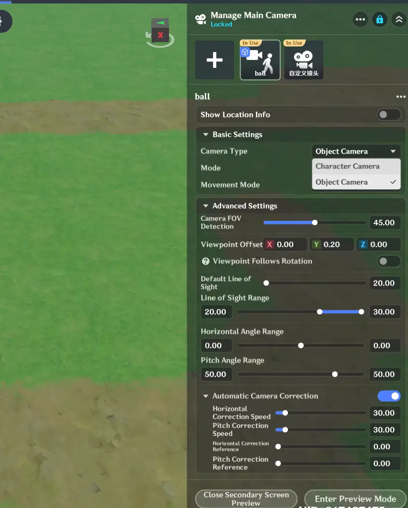
Add a camera and set it as an object camera. I chose a fixed top-down angle to observe the sphere. These parameters may not be optimal — if you're interested, feel free to adjust them yourself.
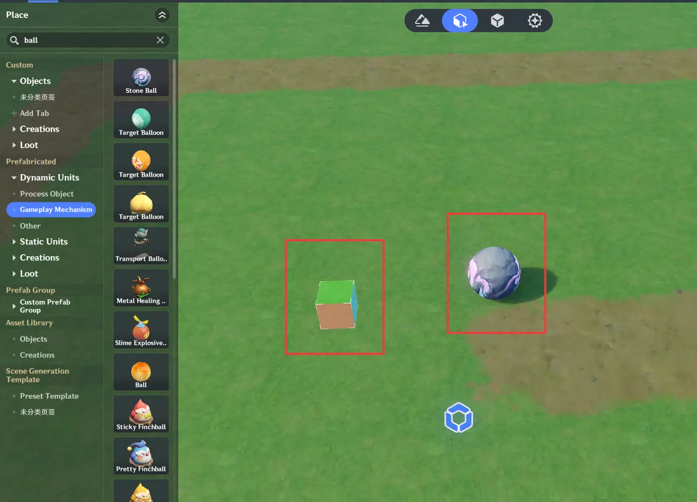
In the scene, add two objects:
- An empty model — used for binding the camera.
- A stone ball — note that you need to set its Y offset to +0.84 so it sits flush on the ground.
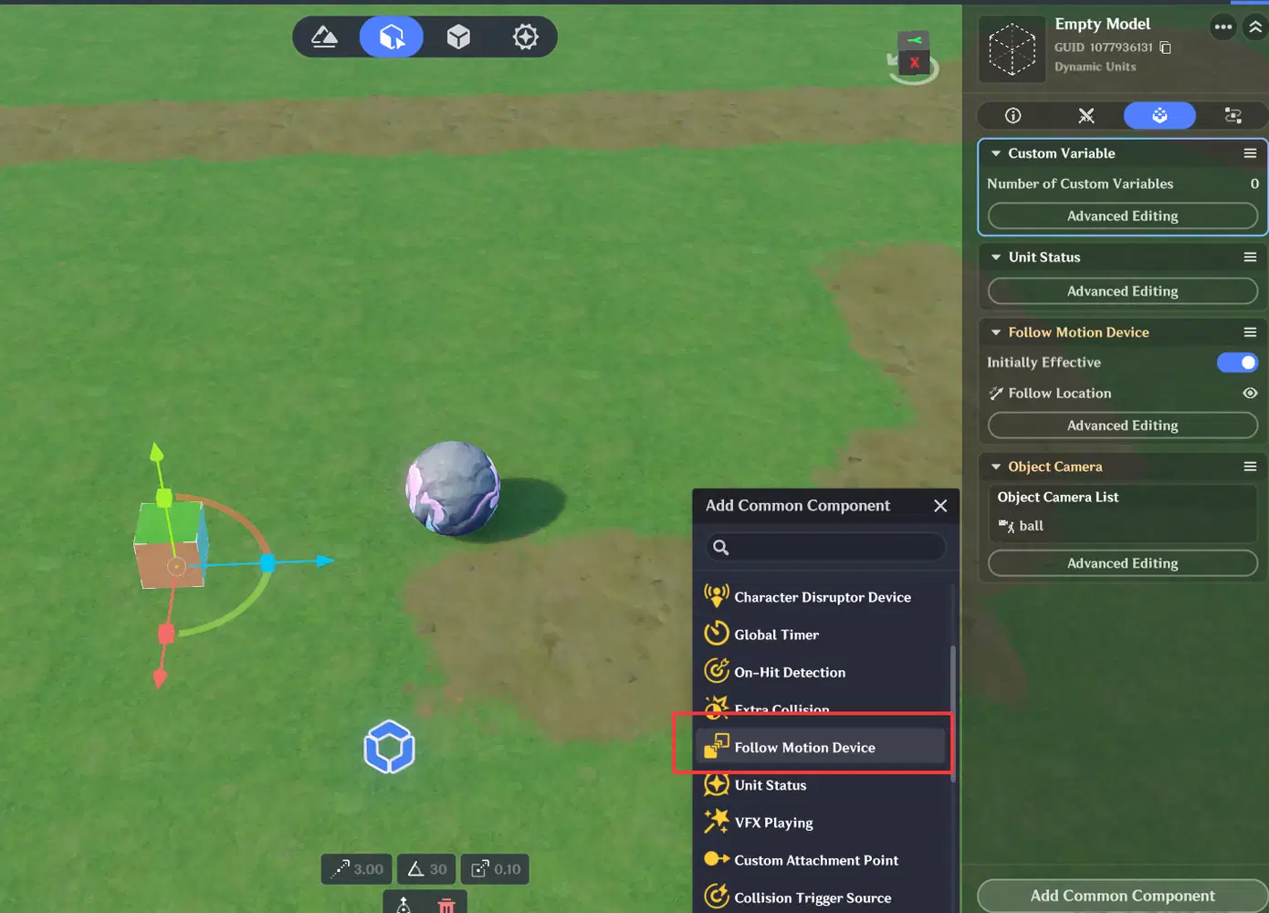
Add a follow motion device to the empty model.
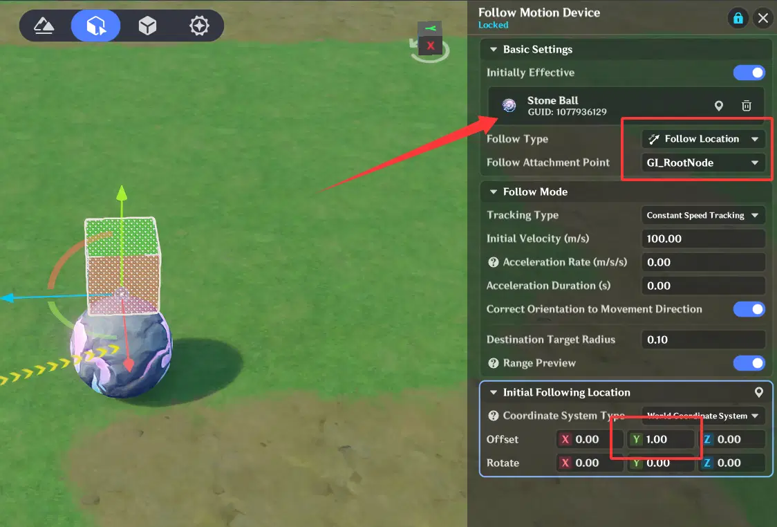
For the follow motion device, we only need it to follow the position — do not make it fully follow everything!! It's recommended to add a slight upward offset to the position.
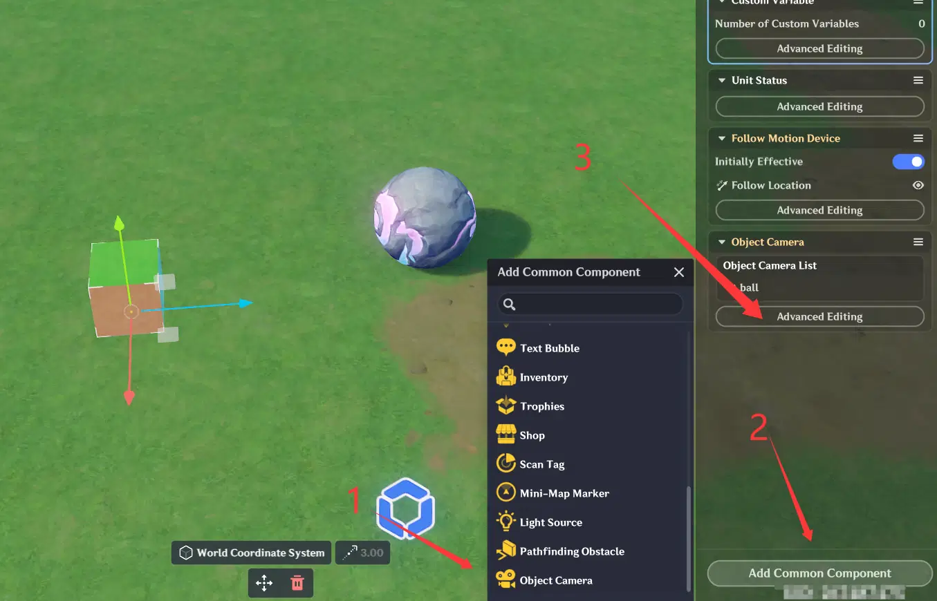
Next, add an object camera to the empty model.
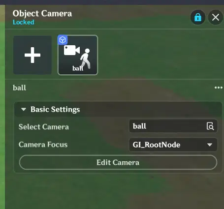
3.2 Create and bind the node graph.
Next, create a node graph and attach it to the player entity. The content is very straightforward — the operation graph is provided directly below.
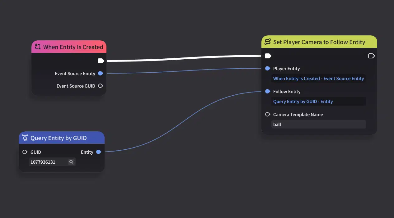
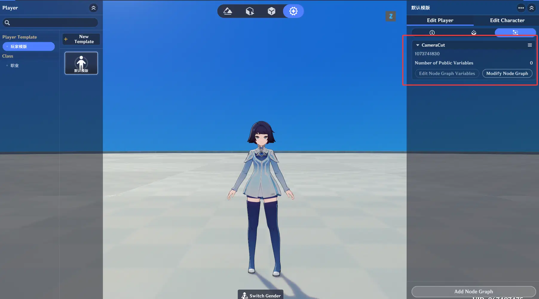
Now you can launch the game to test it — is the camera looking down at the ball from a top-down view?
4. Basic Deceleration Movement for the Ball
This step mainly implements inertial deceleration for linear movement. The system does not provide a built-in deceleration option, so the common approach is to frequently refresh the linear motion device, changing the speed each time to achieve a deceleration effect.
The deceleration effect is achieved by reducing the speed value bit by bit during each update (tick signal) until it reaches 0.
This step is divided into two parts: basic implementation and optimization.
The basic implementation is very straightforward:
- Set an initial velocity and add a basic motion device.
- Reduce the speed by a certain amount during each update.
- Continue until the ball comes to a complete stop.
4.1 basic implementation
Add a basic motion device to the ball. You only need to have this component added — the specific motion device settings will be configured in the node graph.
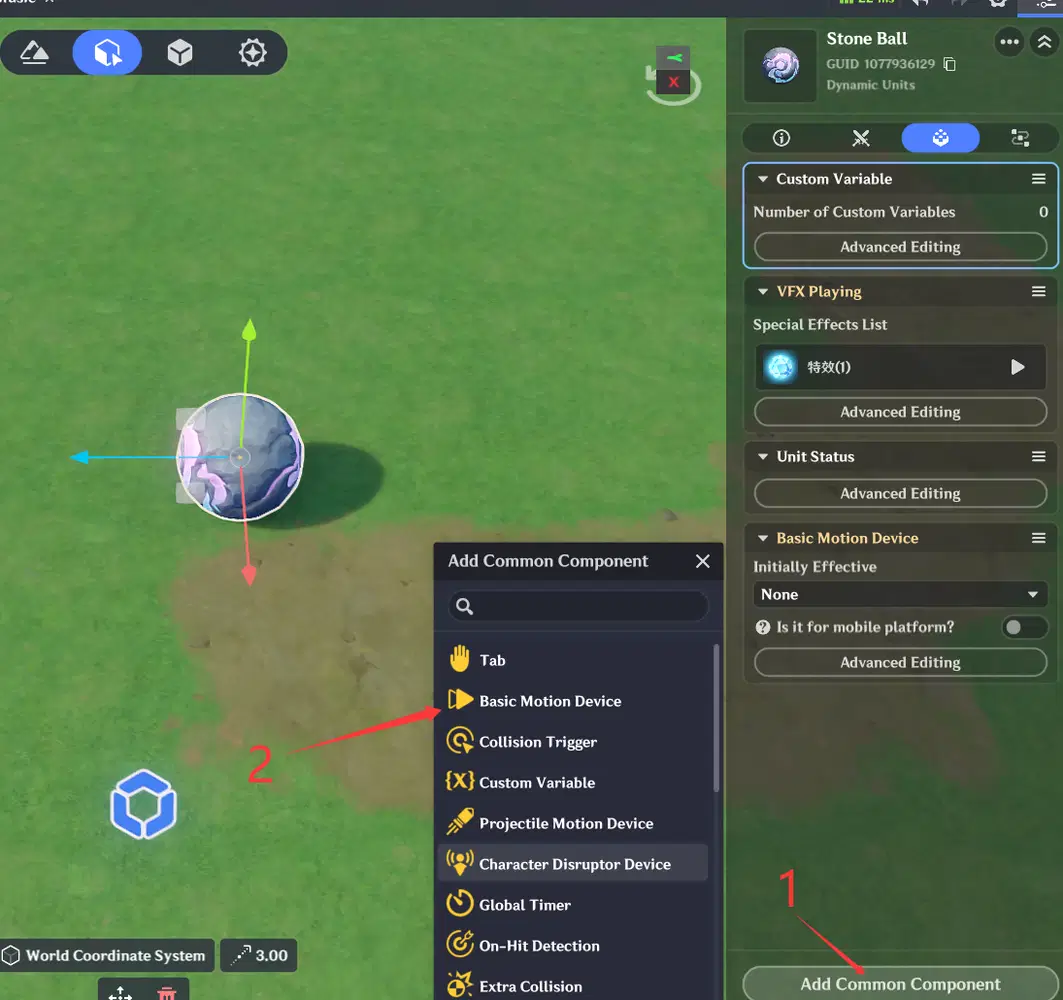
For easier testing, let's use a tab to set the ball's initial movement state. So now we need to add a tab component.
Don't forget to enlarge the tab area, otherwise it will be very hard to click.
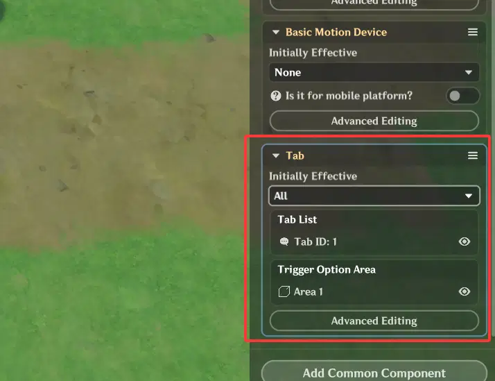
Next, create a node graph to add power to this simple movement!
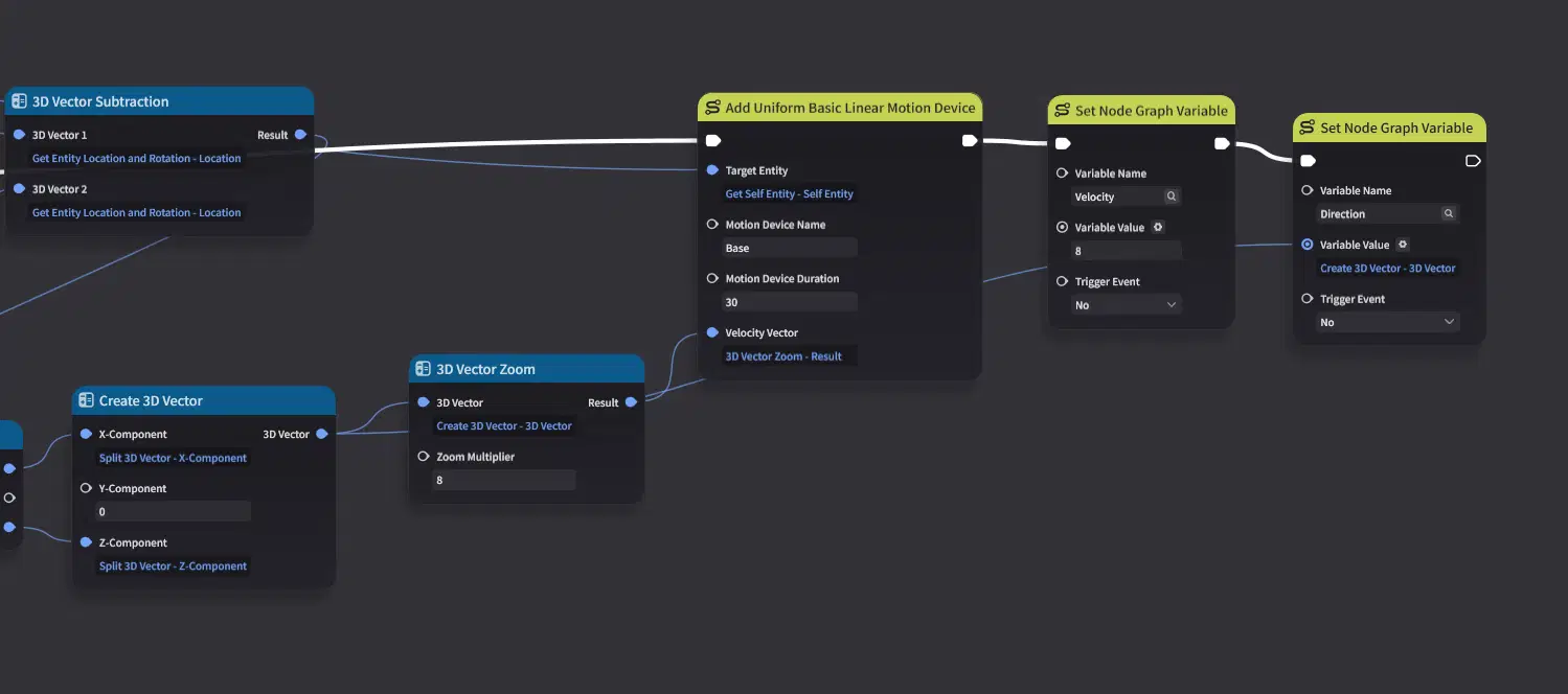
4.1.1 Add a linear motion device through the node graph.
When the tab is triggered (when tab is selected), we calculate the ball's position minus the character's position.
This gives us the direction from the character to the ball. Since we're dealing with planar movement, we simply set the Y-axis component to 0.
After scaling the direction vector, we get the velocity vector required by the base linear motion device.
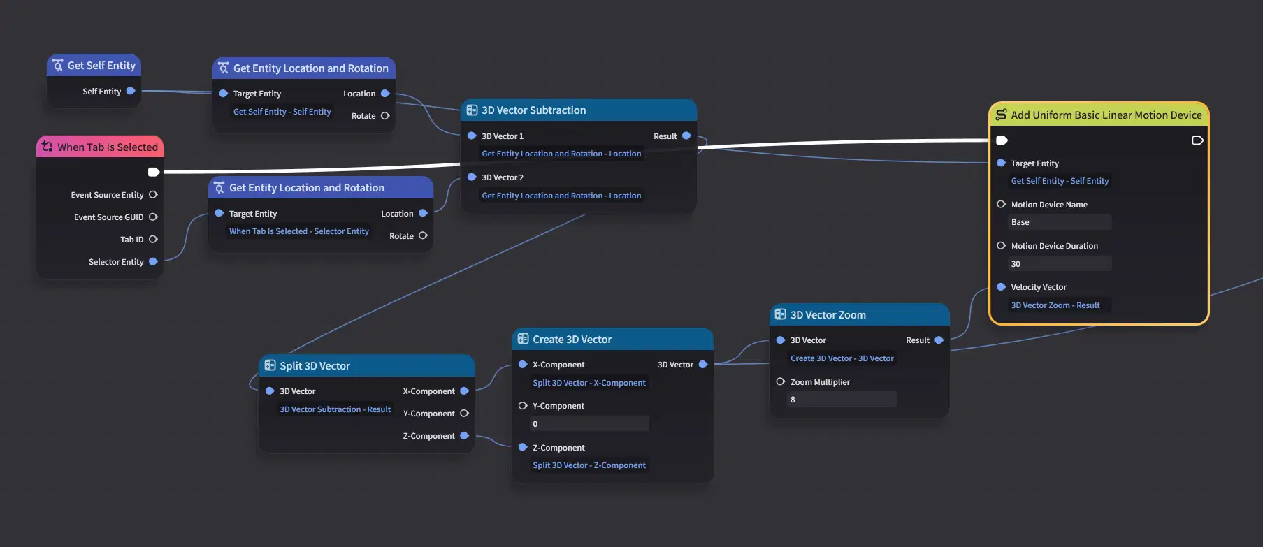
4.1.2 Create a tick signal
Each deceleration step requires a signal to trigger it, so we need to create a looping timer to ensure a steady signal trigger.
Create a signal with no parameters.
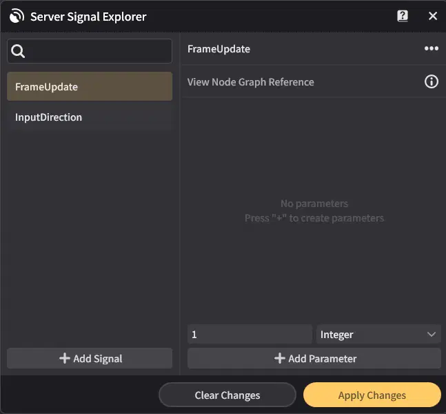
Create a looping timer, and send the update signal when the timer triggers.
In Miliastra Wonderland, the actual timer interval in runtime has an additional 0.03s overhead added to your input value. Therefore, to achieve our target interval of 0.09s (11.11 FPS), we must set the input value to 0.06s (0.06 + 0.03 = 0.09).
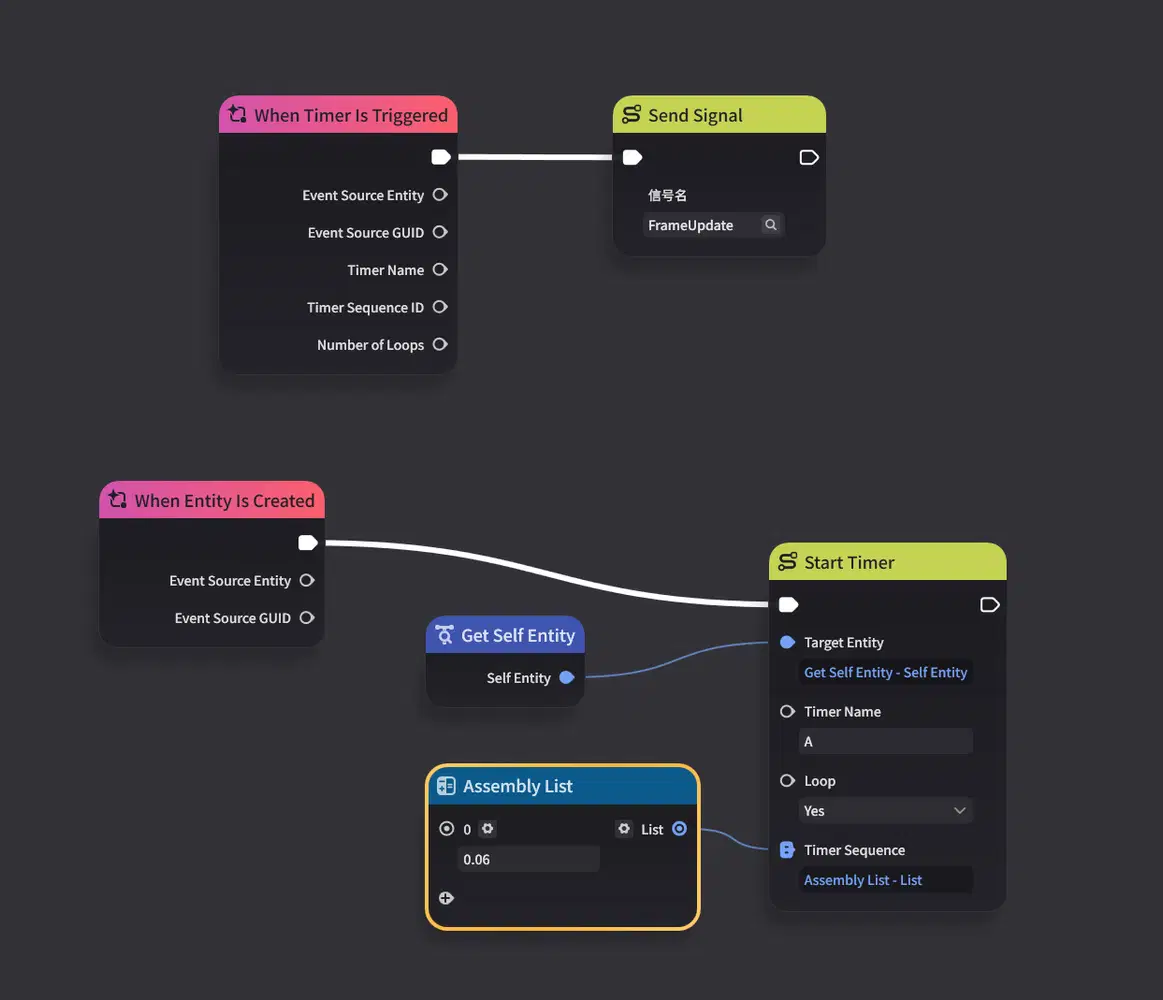
Place this signal update node graph in the level, and you'll be able to get a stable update signal.
4.1.3 Decelerate when the update signal is received
Before that, let's create two node graph variables first. Since they will be used in every update, using node graph variables is a good way to handle them.
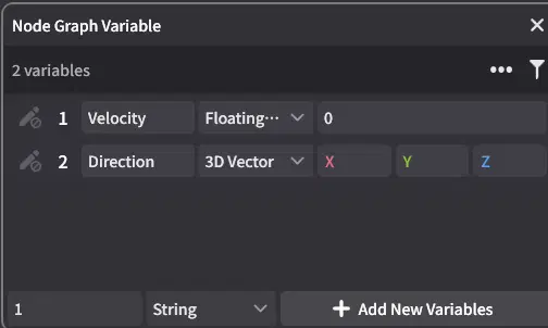
At the same time, when the tab is triggered, synchronize the data to the node graph variables as well.
Next, let's handle the update event:
Next, let's handle the update event:
In this event, we perform two checks.
- The first check is whether the speed is greater than 0. This step mainly prevents unnecessary performance consumption.
- The second check is whether the speed, after decay, is still greater than 0. We must ensure the ball's speed is always either 0 or positive.
When it reaches 0, it means it's time to stop. So in our logic: if it's greater than 0, we update the movement; if it's less than or equal to 0, we stop the motion device and set the variable to 0.
In the node graph, we set the deceleration to 0.3 per update, so the ball will come to a stop very quickly.
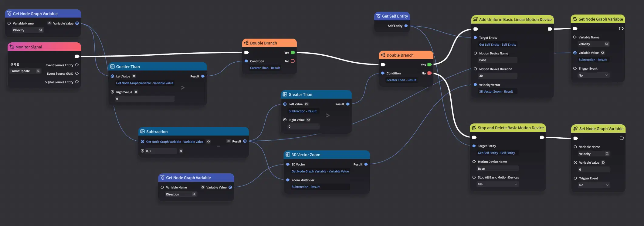
Next, place the node graph on the ball. If everything is set up correctly, now when you press the tab, the ball will move and then decelerate to a stop.
4.2 Deceleration Curve
4.2.1 Deceleration Curve
In this sub-section, we'll move away from the simple fixed deceleration approach.
Instead, we'll use a three-stage speed control system to simulate deceleration that feels more natural and intuitive:
- Percentage-based deceleration — This stage mainly controls the absolute value at high speeds. When the speed is too high, a simple fixed subtraction cannot easily adapt to different speeds.
- Fixed value deceleration — The core speed control stage.
- Low-speed decay — In real-world physics, low speeds introduce significant rolling friction. This parameter mainly controls how the object comes to a stop.
The final deceleration curve will look roughly like the following, and by parameterizing the values for each segment, we can easily control the slope and magnitude of each part of the curve. This leaves plenty of room for adjustment.
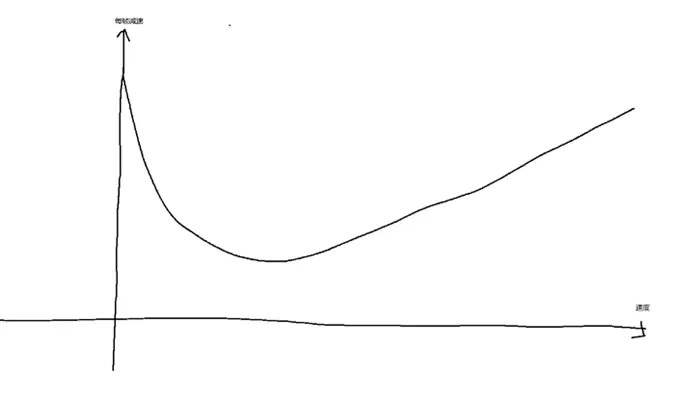
In the high-speed segment, we primarily use only linear control, so the actual deceleration effect during runtime is relatively limited. This is because our demo does not require heavy penalties for high speeds. If you wish to impose stricter penalties on the high-speed segment, you can introduce a quadratic function. This will not be covered here.
4.2.2 Actual Implementation
Let's first outline the deceleration formula:
When speed > low-speed intervention threshold:
Fixed deceleration coefficient + Speed × Percentage coefficient
When speed < low-speed intervention threshold:
Fixed deceleration coefficient + Speed × Percentage coefficient + (Low-speed threshold - Current speed) × Current speed
The formula is relatively simple, but we need to map it into the node graph.
Encapsulate this formula through a node graph for later use:
- Input: Speed
- Two outputs:
- One without low-speed influence
- One with low-speed influence
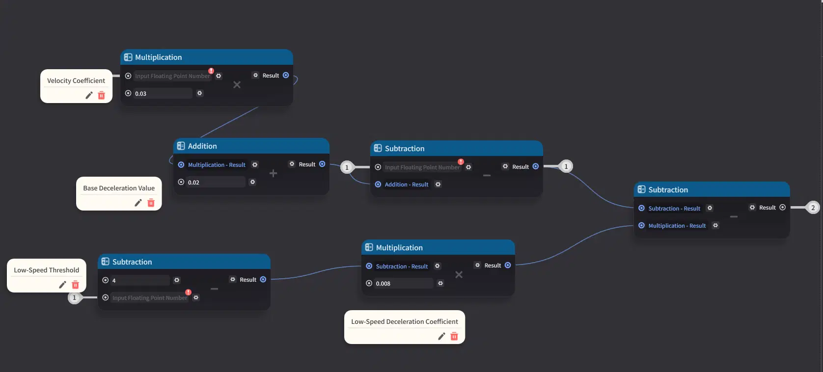
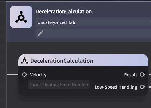
Now we've made some changes to the deceleration nodes, but the overall logic remains the same: first calculate the deceleration, then go through the same checks as before.
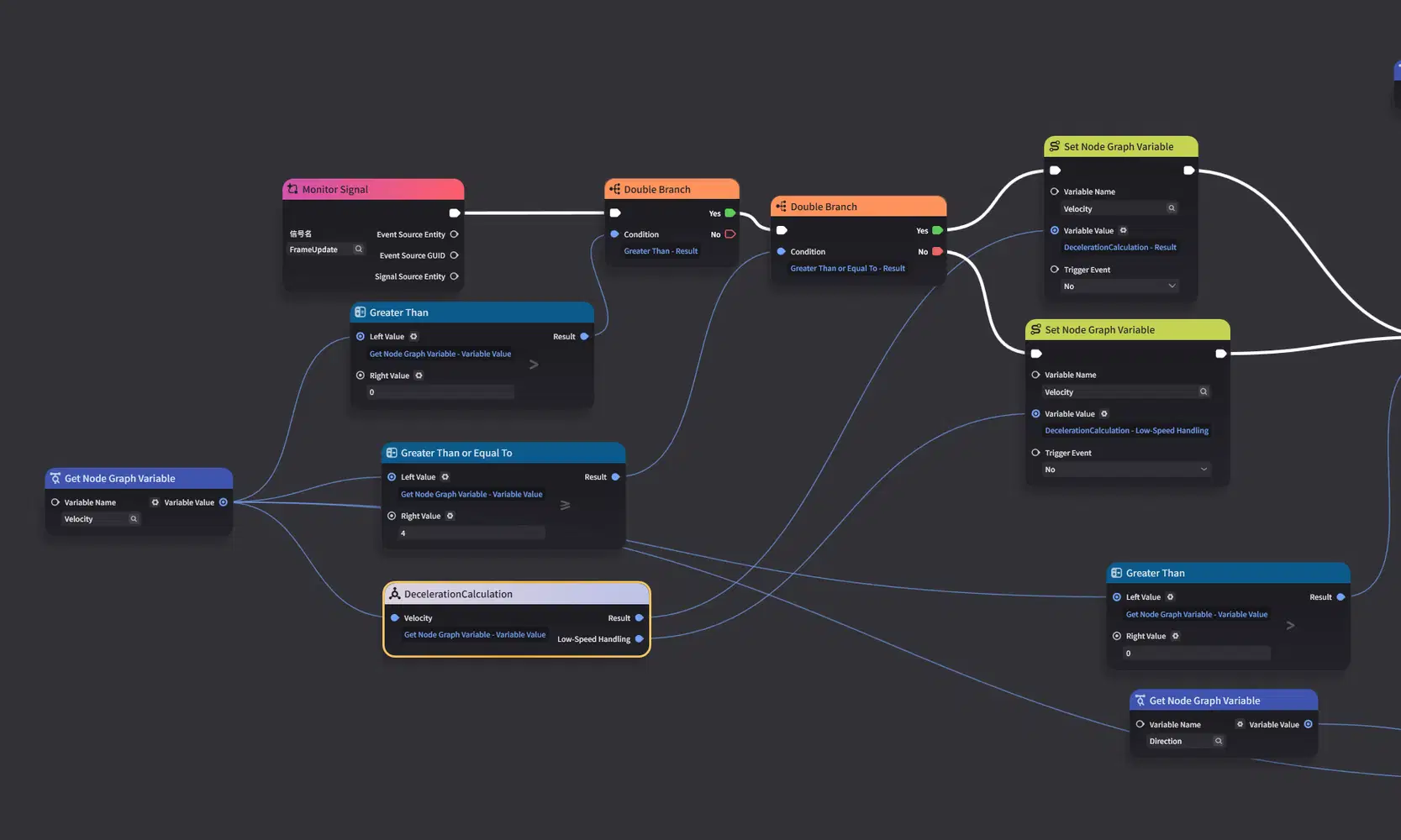
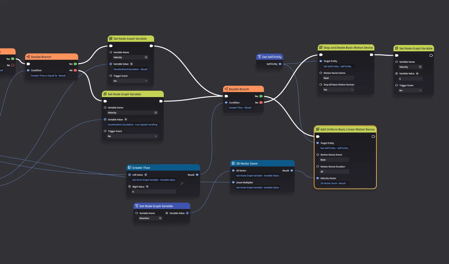
4.2.3 Why Do It This Way
I'm sure you can feel that introducing a calculation that seems almost no different has significantly increased the node complexity.
So why do it this way?
Simply put: to simulate a better deceleration effect. A fixed deceleration value gives a very artificial feel. In other words, by designing deceleration with a function curve, we can fine-tune it to achieve a more realistic and premium sensation.
5. Input Action Accumulation (Acceleration Effect)
5.1 Overview & Principle
Finally, we've reached the part where our actual input takes effect.
Just like deceleration, we achieve acceleration by accumulating changes during each update.
The maximum update frequency per second is the same as that used for deceleration.
The main task is actually to calculate: converting the input from the range [-180, 180] into a direction vector. Then, simply multiply the acceleration coefficient by the input direction vector to get the velocity vector delta.
Adding this to the current velocity vector gives us the speed change for a single frame.
So, let's get started!
5.2 Implementation
Similarly, add an input signal listener to our ball's node graph.
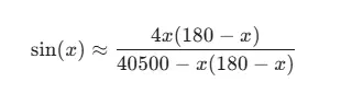
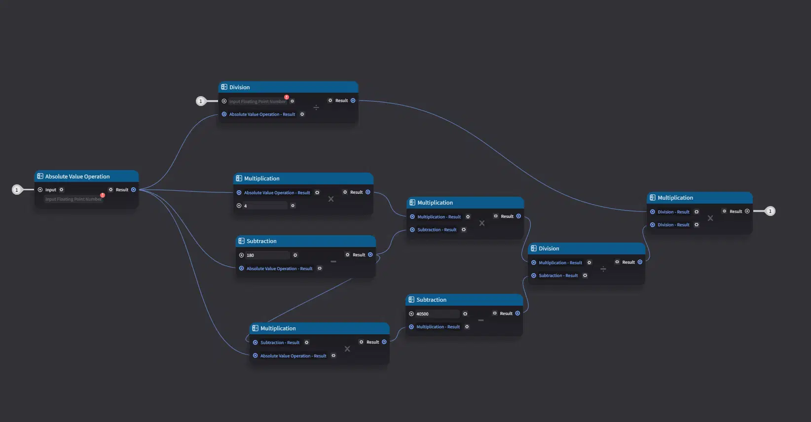
Bhaskara's Approximation:This is a method for quickly approximating trigonometric functions. Proper use of it can help us achieve 3D vector conversion at low cost, thereby supporting omnidirectional steering via the wheel input. In terms of precision, it fully meets our steering requirements.
Bhaskara Node Graph Implementation:
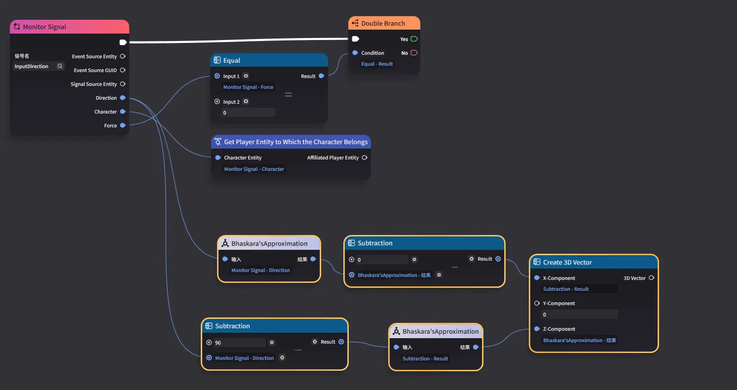
Input direction value (raw value) — Solve for the input direction vector.
Calculate the accumulated value: We need to set an acceleration coefficient to compute the acceleration value for each update. Don't forget to use the strength to scale the vector — this easily supports variable strength input. Finally, normalize the 3D vector to serve as the direction, and take the magnitude of the 3D vector as the speed.
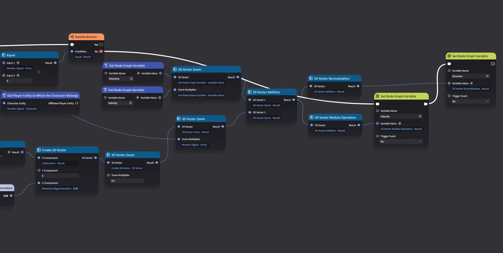
Note: During acceleration processing, we do not directly update the motion device. Instead, we wait for the next deceleration update. This may introduce a delay of 1-2 frames due to network and frame synchronization, but in continuous inertial movement, this delay is practically imperceptible.
Remember our deceleration handling? The faster the speed, the stronger the deceleration. Meanwhile, the acceleration we've implemented is constant, so the ball won't accelerate indefinitely — the deceleration parameters you set will also affect the ball's maximum speed.
5.3 Ball Rotation
In Miliastra Wonderland, basic motion devices can be stacked, meaning we can directly add a rotational motion device on top of a moving sphere.
We simply need to calculate the rotation axis and rotation speed based on the velocity and the ball's movement direction.
Now let's start modifying:
First, solve for the rotation axis based on the direction and the ball's own rotation.
Hmm, to be honest, if you have decent linear algebra knowledge, I probably don't need to explain this. If you don't, don't worry — just use it directly!
- Input: Velocity
- Output: Axis
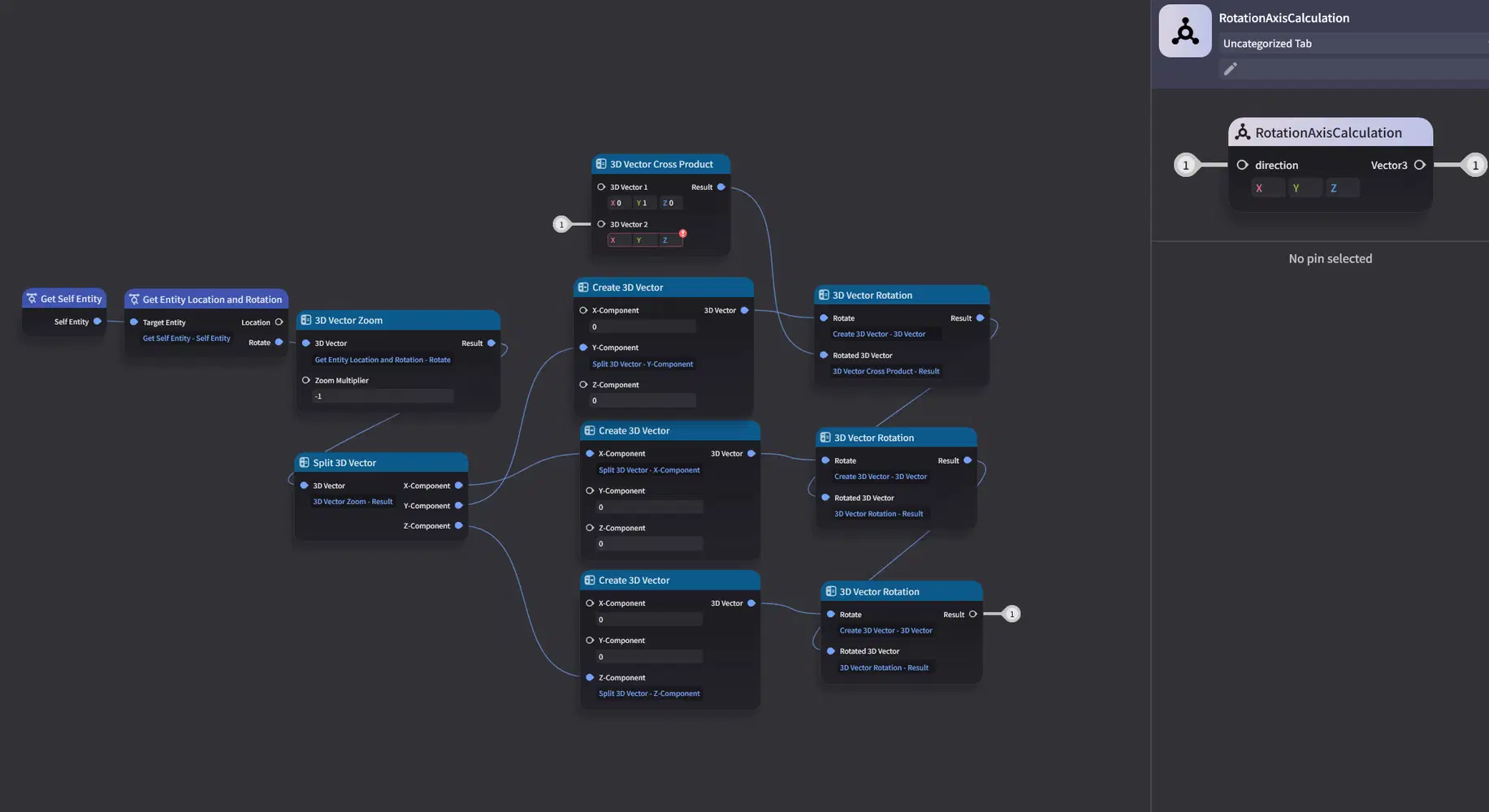
Input: Velocity, Output: Axis
Use speed × 75 (you can modify this — it will determine whether the rotation is fast enough) as the rotation speed, and the calculated axis as the input.
Also, don't forget to remove the rotational motion device when the ball stops as well.
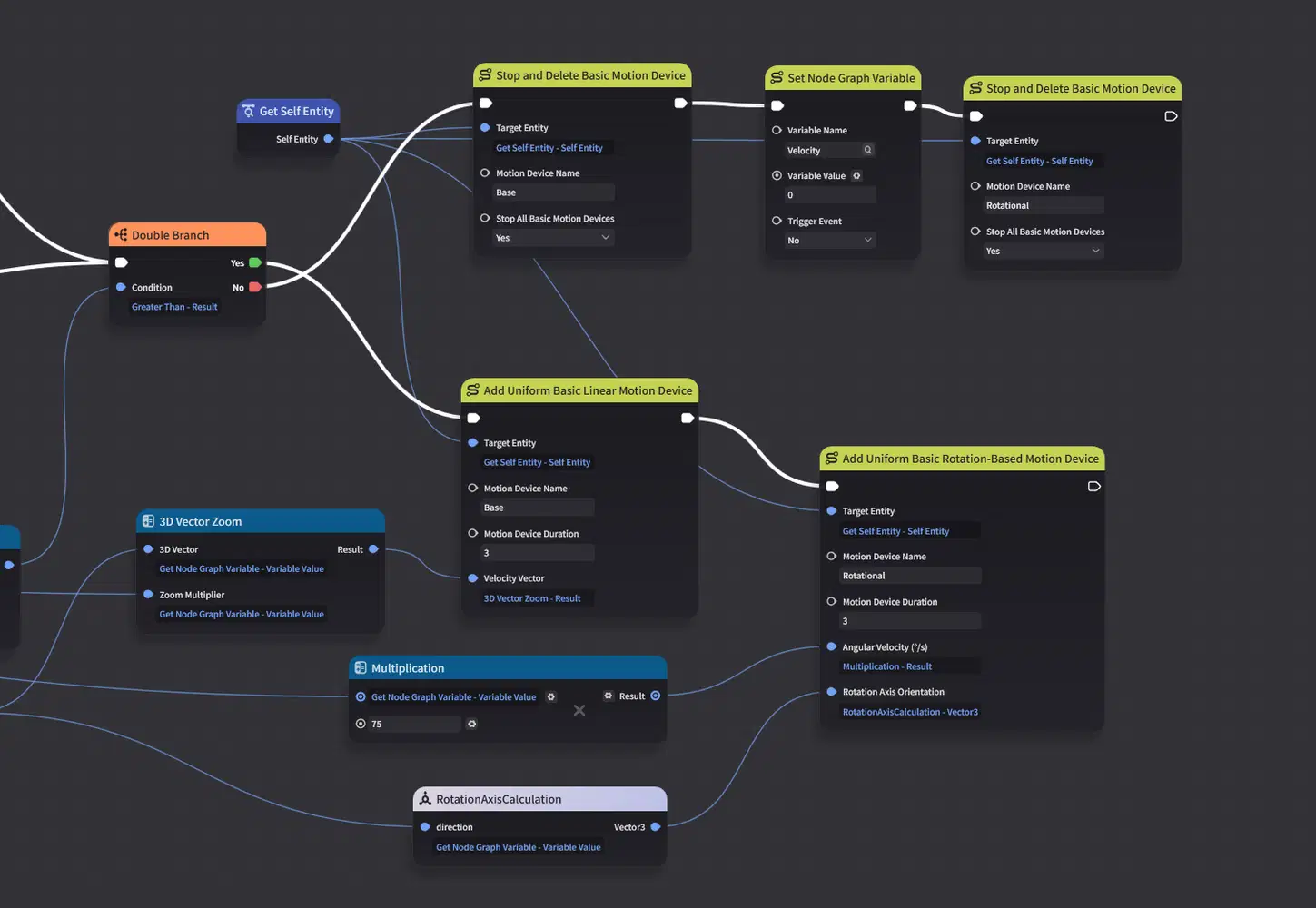
As for the tab component, you can now remove it. We no longer need it.
6.Lock the main character away.
This essentially still captures the character's movement input, and if not locked away, the character will run around uncontrollably.
Just place it somewhere out of sight and hide the model — that will do.
It's cruel, but sorry!
This concludes the guide. I hope you found it helpful!
Since this is a tutorial, some parts of the implementation have been simplified. The version available for download in the Asset Center is the complete version — similar in functionality but more polished.