This tutorial will walk you through, step by step, how to build a fully functional basic roguelike combat system in Miliastra Wonderland. We’ll also touch on some fundamentals of roguelike game design.
We’ll break the system down into several sections:
- Enemy Spawning and Death Tracking
- In-Run Upgrade Design
- State Cleanup
- Game Items
- Meta-Progression
- UI
Since this is primarily a tutorial, we won’t go too deeply into expanding the gameplay itself. Instead, the focus will be on how to implement each system smoothly in Miliastra Wonderland.
This tutorial is mainly aimed at beginner to intermediate Craftspeople, with an emphasis on covering how the different modules are used and how they work together.
With that, let’s get started!
1. Preparation
1.1 Setting Up the Scene
To make setup and testing faster and easier, we’ll use a combat scene from the Asset Center. You can quickly download it here: Combat Scene Asset
Next, create a blank Stage. Since these steps are fairly basic, we’ll go through them quickly.
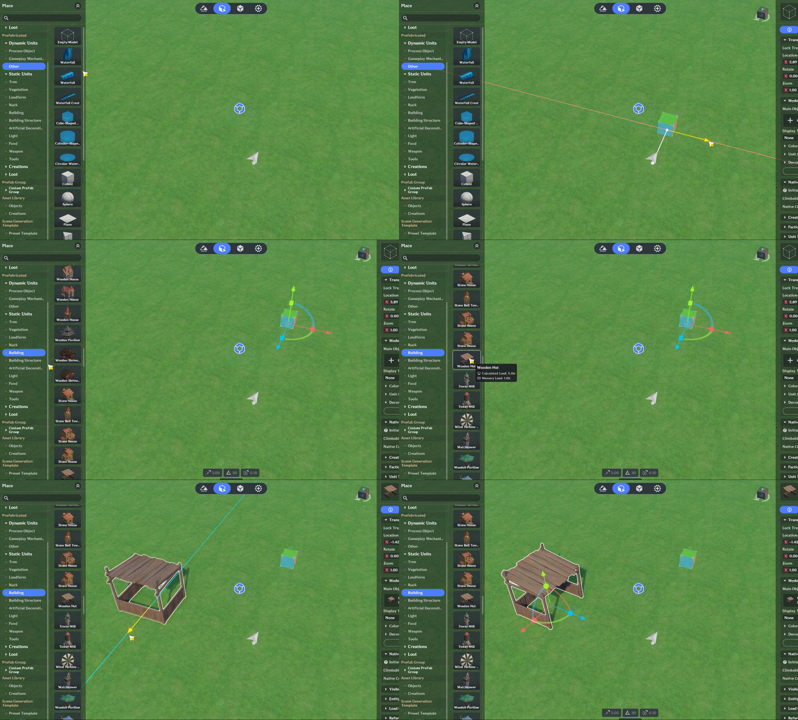
Place a shed and an Empty Model in the scene. These will later serve as the shop and the Stage entrance.
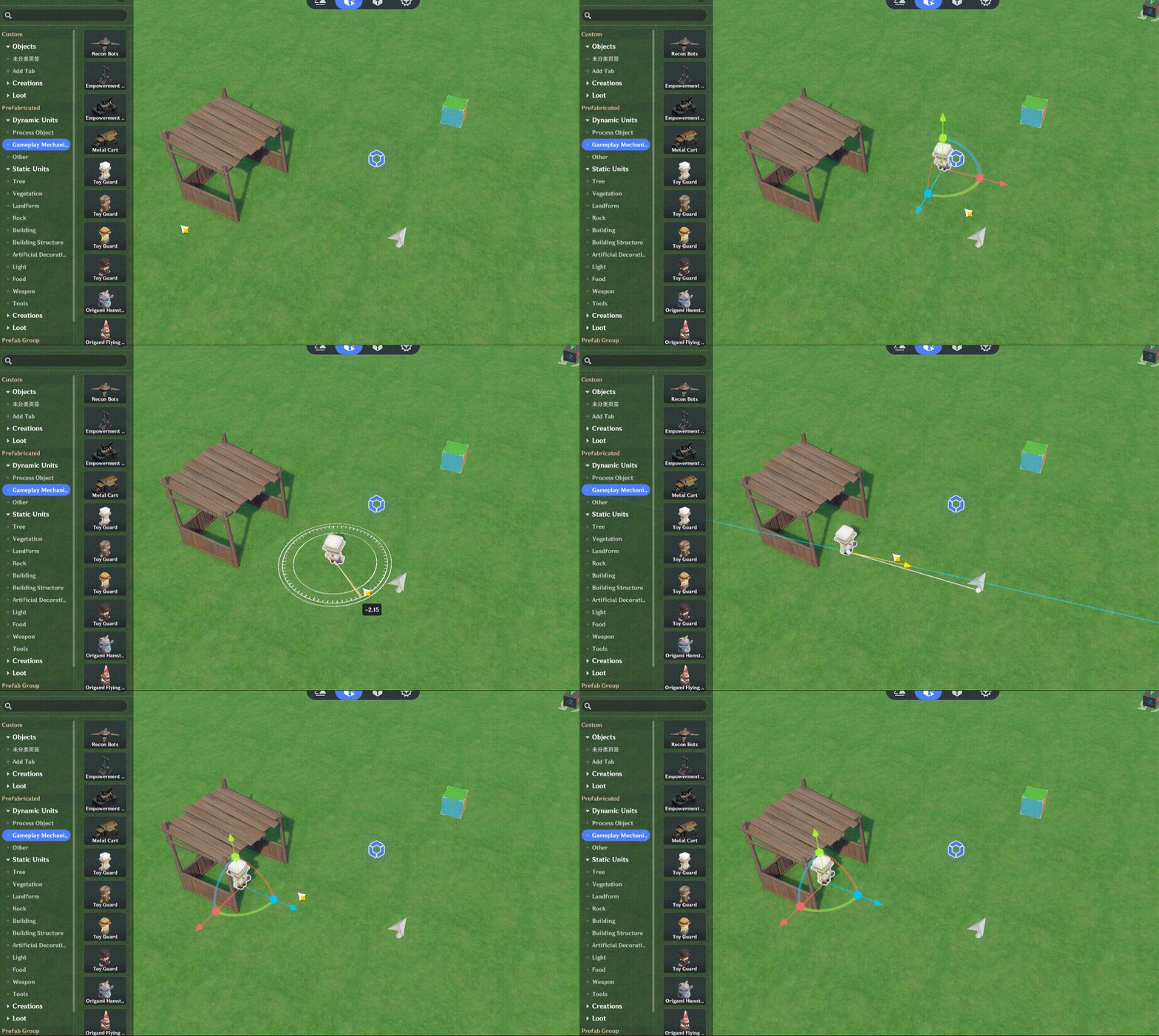
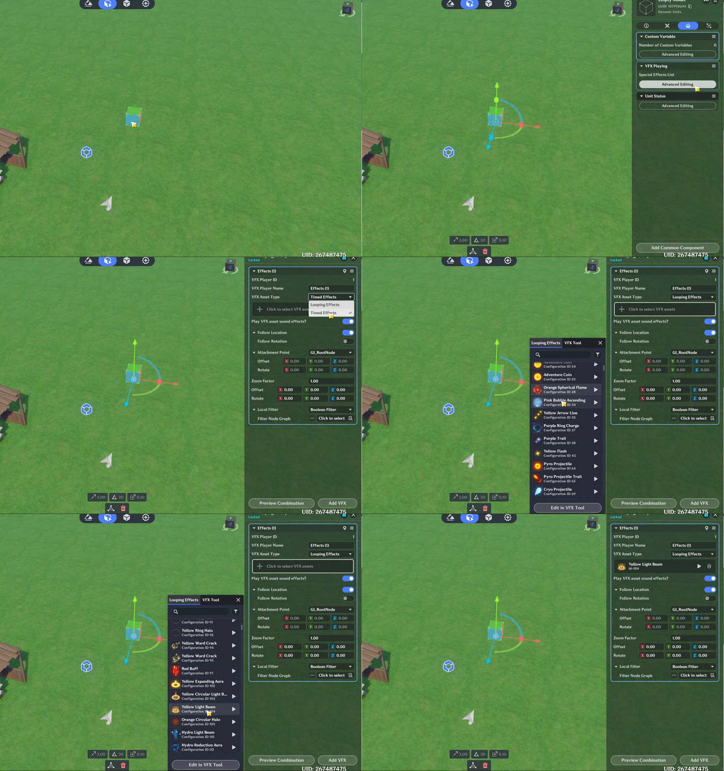
Add a Block Doll inside the shed. It will later serve as the shopkeeper and as an interaction point for other dialogue-based features. Then, select the Empty Model at the Stage entrance and give it a suitable looping visual effect.
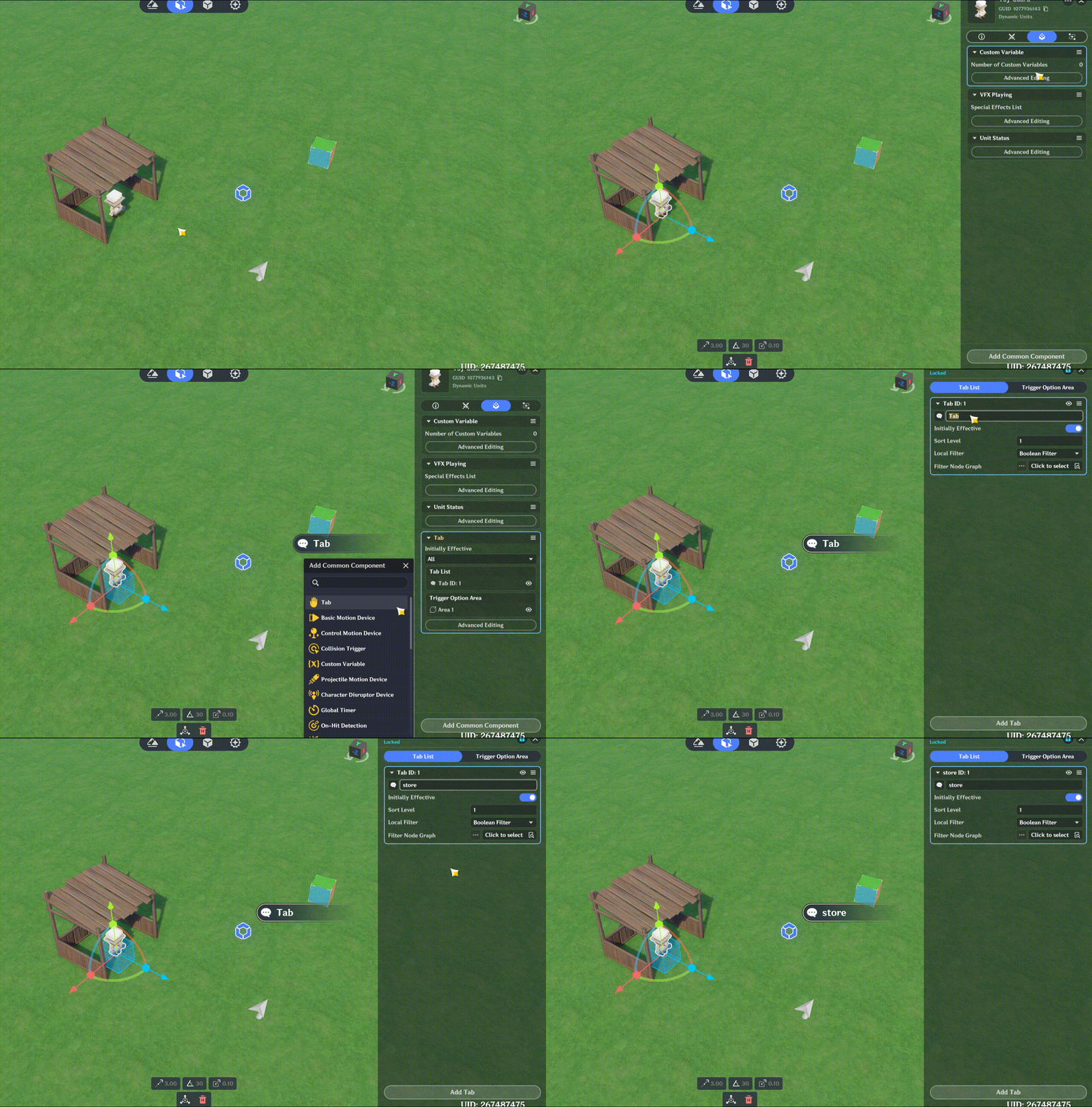
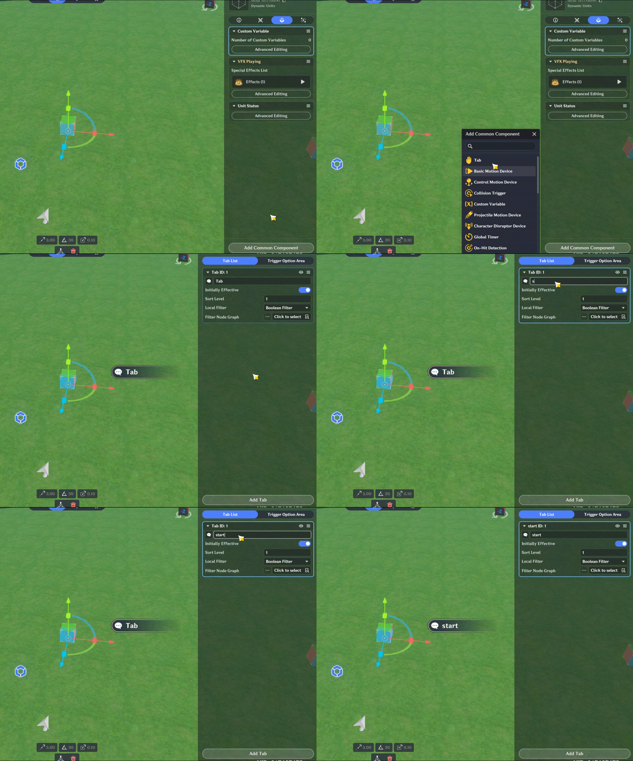
Add a Tab Component to both the Block Doll and the Empty Model. These will serve as entry points for their respective features later on.
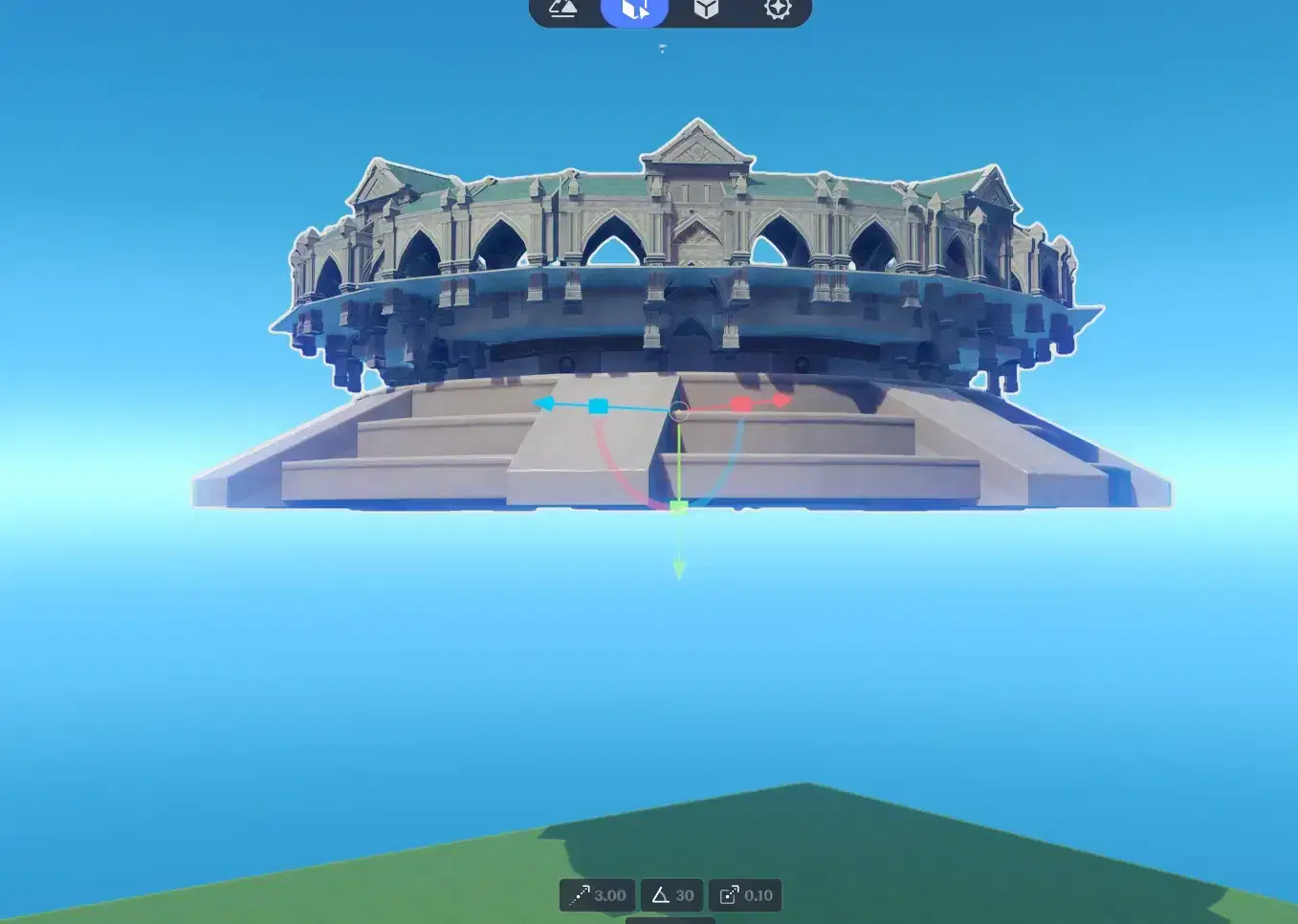
Import the asset we downloaded. Make sure to place it in the designated directory provided by the editor. Once imported, place it above the current scene.
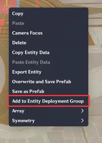
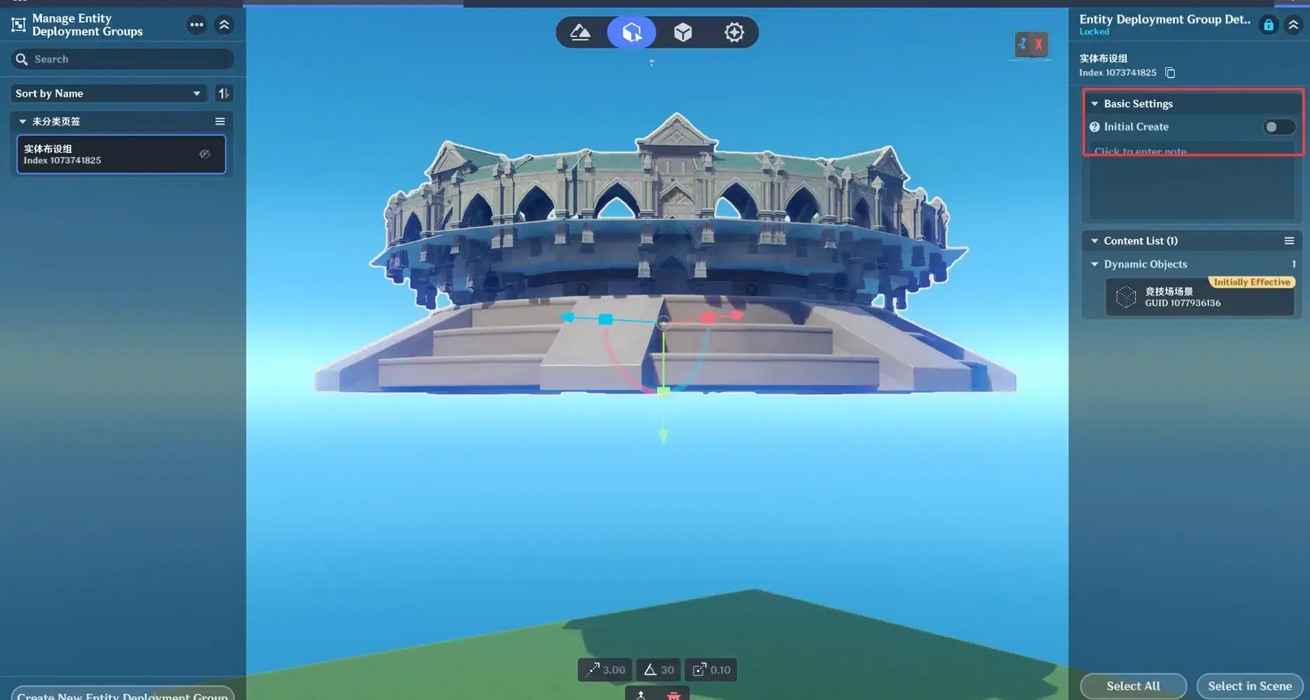
Add it to an Entity Deployment Group and set it to not be created by default. It will only be created after entering the Stage.
1.2 Implementing Teleportation
First, we need to create a Preset Point before setting up the Node Graph.
Navigate to the arena scene.
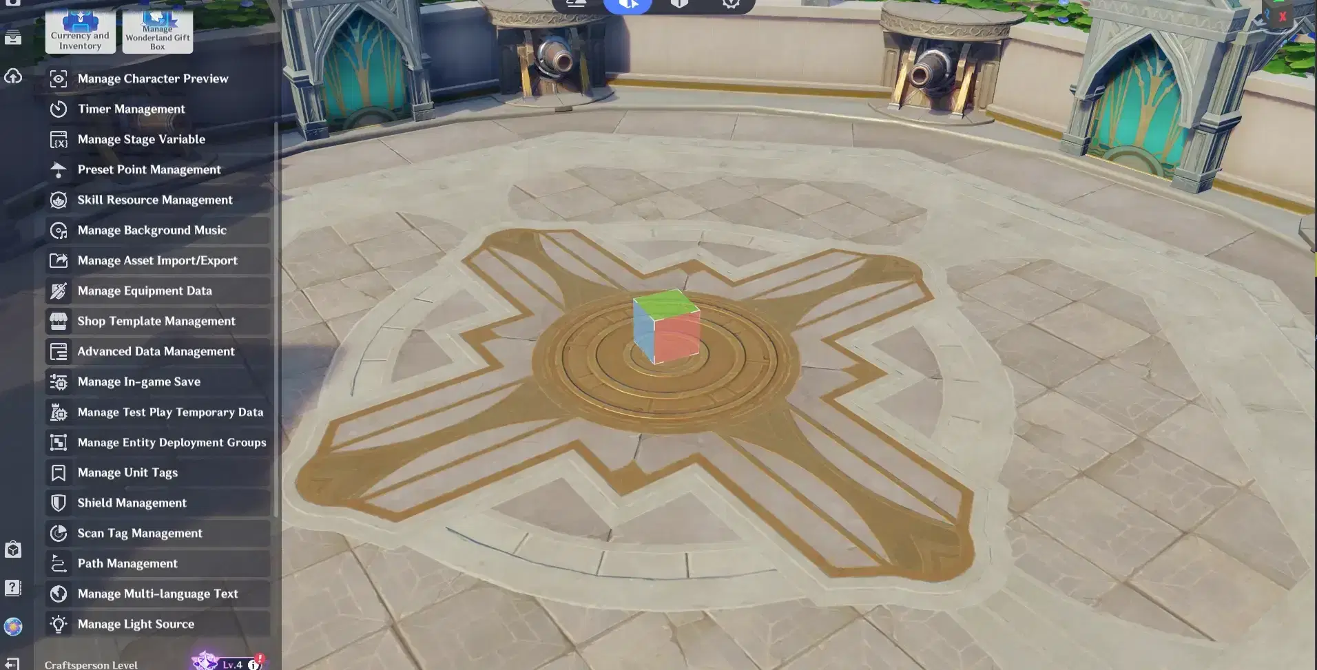
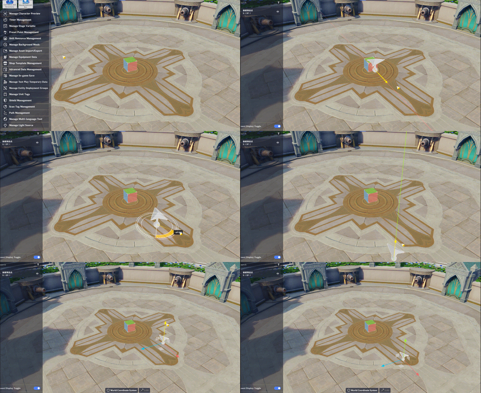
Create a Preset Point on the platform. Make sure to position it slightly above the ground to prevent the player from falling through the floor after teleporting.
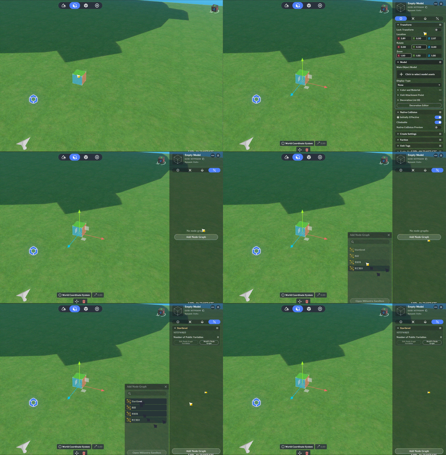
Next, create a Node Graph to implement the teleportation function. Start by creating an empty Node Graph, then bind it to the Empty Model at the Stage entrance.
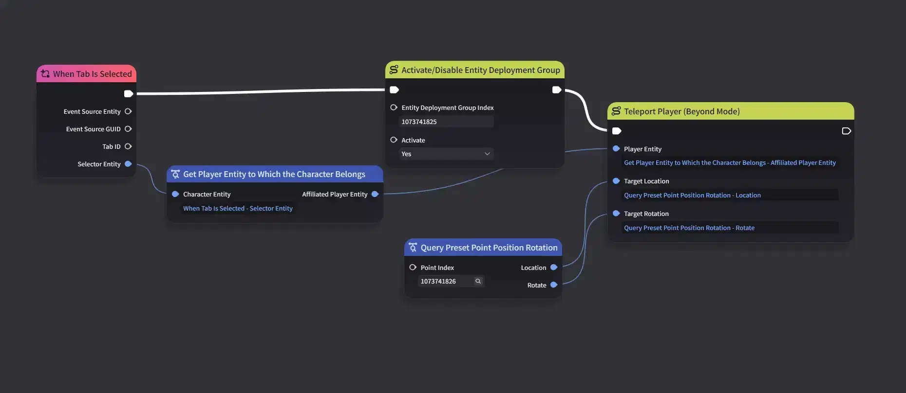
Next, let’s set up the Node Graph.
Keep in mind that our Entity Deployment Group is not created by default, so we need to create the group before teleporting.
Then, get the position and rotation of the Preset Point we just created and use them to teleport the player.
1.3 Testing
Now we can run a basic test. Approach the entrance and check whether the Tab Component is configured correctly, and whether the teleportation and scene are working as expected.
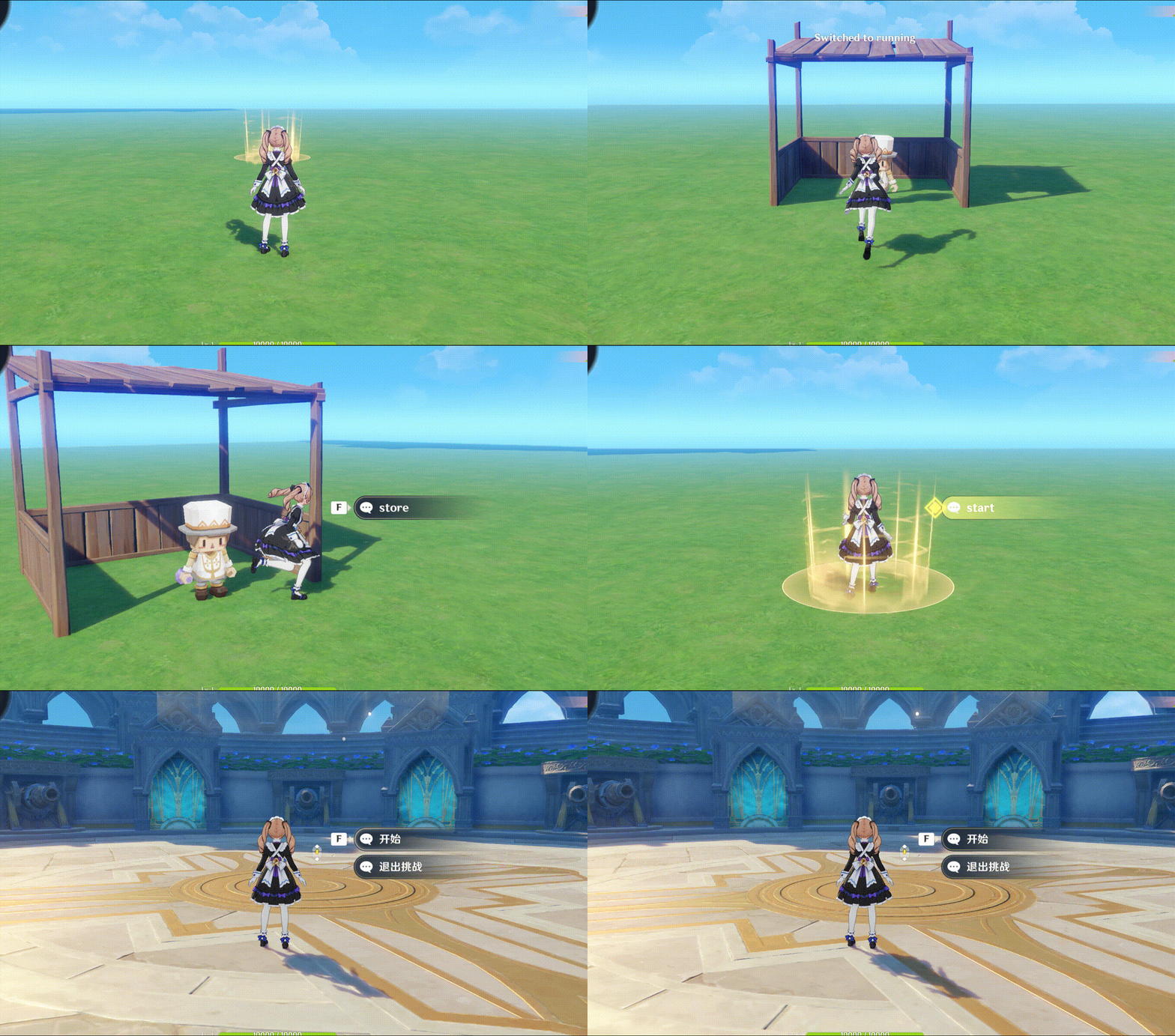
As you can see, the Tab Component, scene, and teleportation are all working correctly!
That wraps up our preparation. Next, let’s move on to implementing the first part of the system.
2. Random Enemy Spawning, Kill Tracking, and Floors
Our Stage follows a fairly simple gameplay loop:
Enter a floor → Spawn enemies → Defeat them → Clear the floor
For enemy spawning, we’ll use fixed spawn points combined with randomized enemy groups and randomized position offsets. Enemies of the same type, such as Hilichurls or Slimes, will be organized into groups. At each spawn point, one of these enemy groups will be randomly selected and spawned.
Once all enemies have been defeated, the Floor count will increase by one, and the enemies will become stronger accordingly.
Now that we have the basic flow figured out, let’s start implementing it. As usual, we’ll break the process down into smaller sections. We’ll also maintain a simple UI display along the way.
2.1 Random Enemy Spawning
Following the design above, we’ll start by setting up three spawn points. We’ll use Preset Points for this, as they are easy to reposition and save us from having to manually enter coordinates.
2.1.1 Preset Points and Tab Component
The setup process is fairly straightforward, so we’ll skip the animated demonstration here and go straight to the result.
Place three Preset Points at three different positions, with each one facing toward the player.
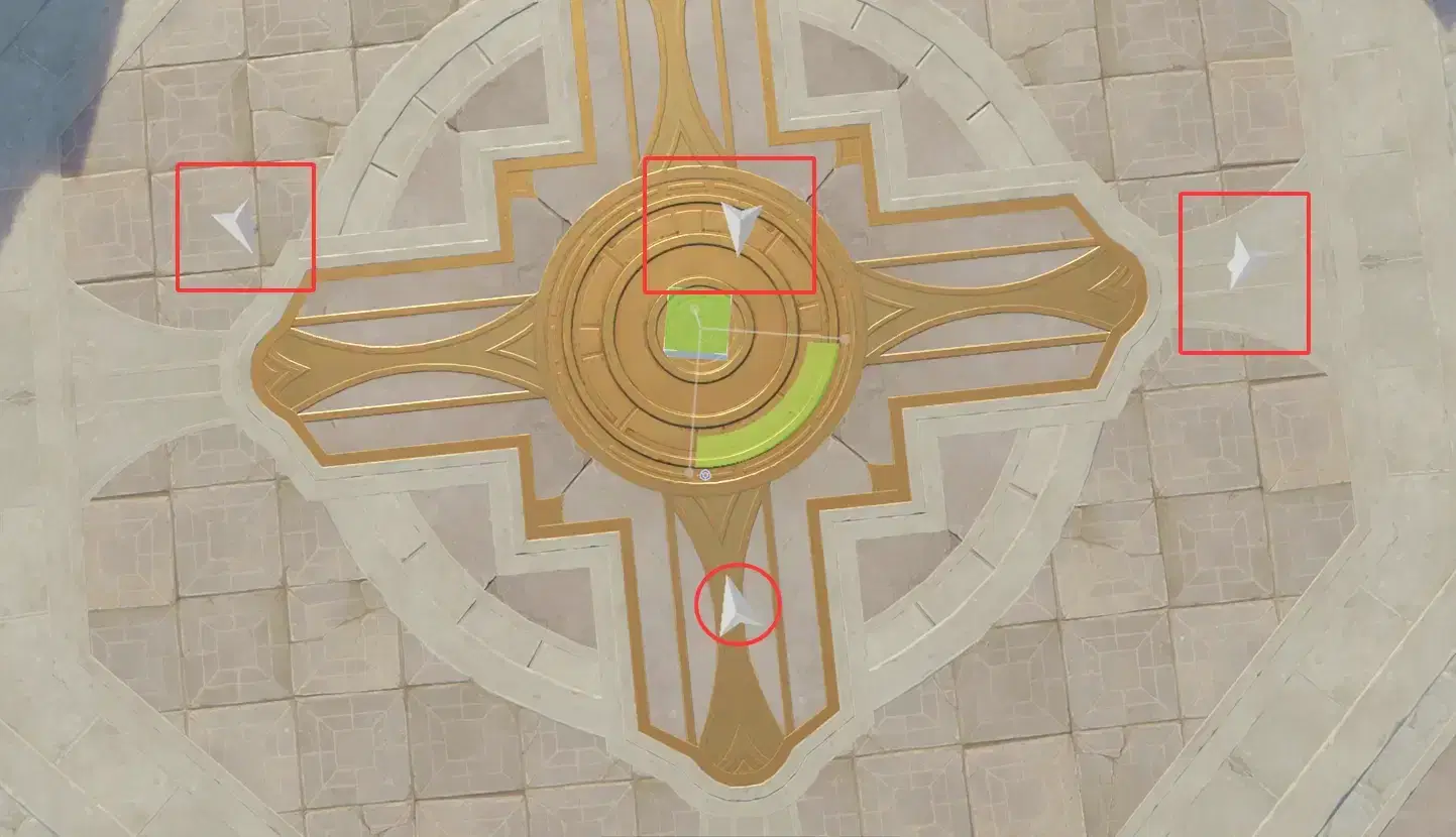
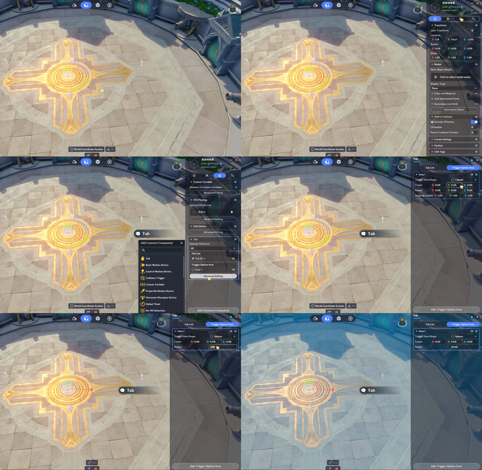
Next, create a Tab Component in the arena.
Unlike the other Tab Components, we want this one to be accessible from anywhere in the arena. Set its activation range to a circle with a radius of 20.
2.1.2 Editing the Node Graph
In this section, we need to accomplish several things:
- Set up the predefined enemy group data
- Start the game and spawn enemies through a Tab Component event
- Track the player’s state to control whether the Tab Component is shown or hidden
As mentioned earlier, enemies will be defined in groups, so we need to configure these enemy groups in advance. The visibility of the Tab Component, meanwhile, will be controlled through the player’s state.
First, create a Node Graph and bind it to the arena.
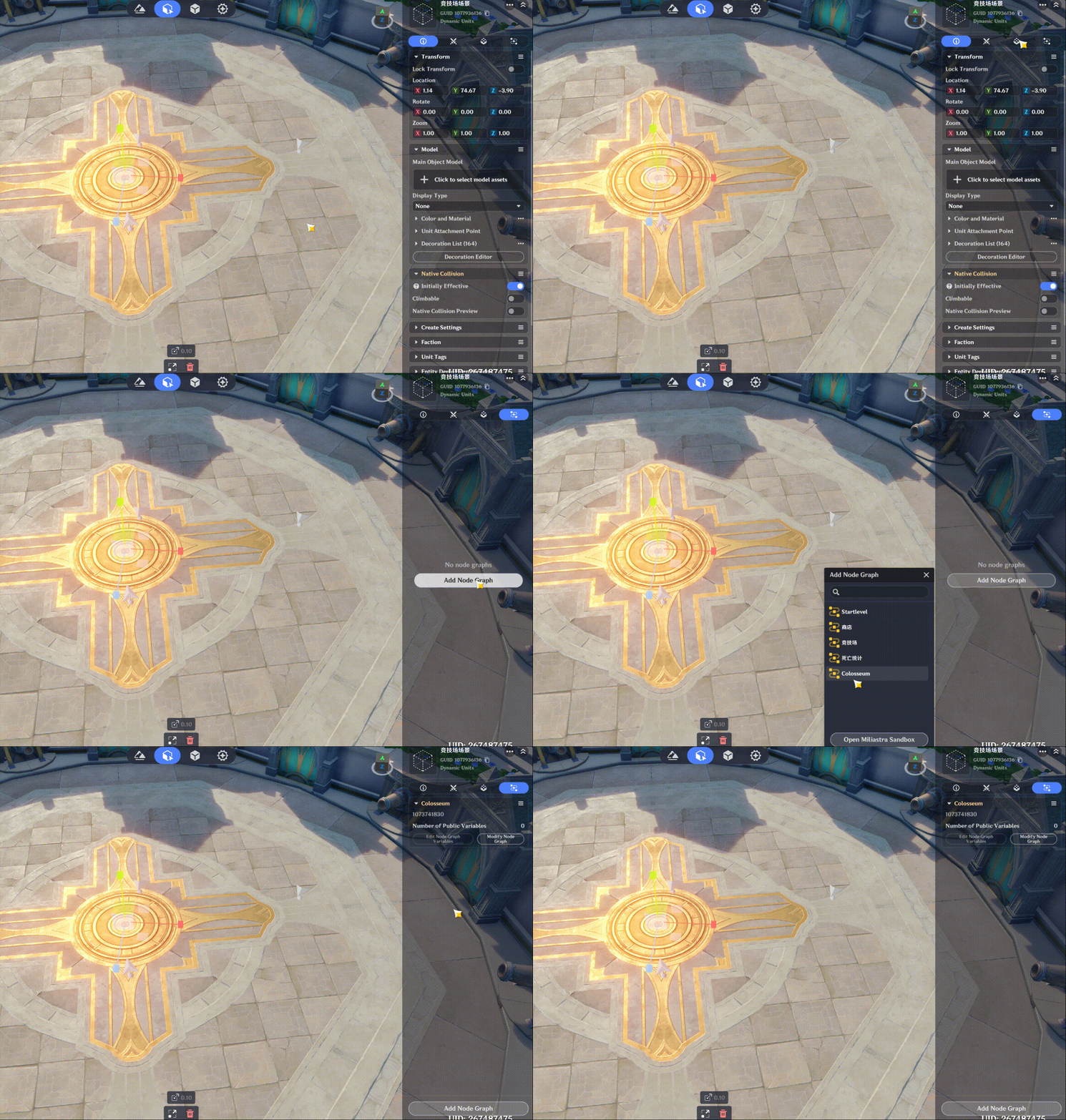
Next, let’s start editing the Node Graph.
First, configure two enemy groups using a Dictionary. The key is the group name, while the value is a list of Component IDs.
We’ll create two enemy groups: Slimes and Hilichurls.
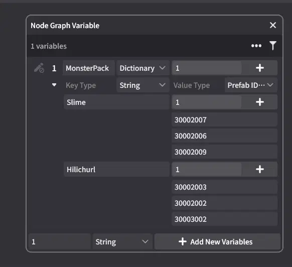
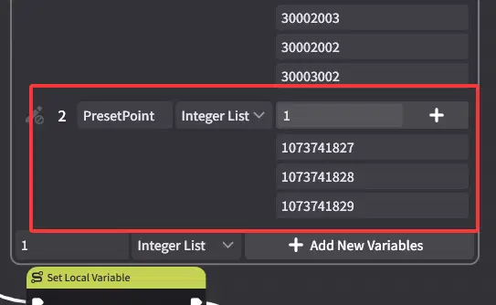
Next, remember the Preset Points we configured earlier? To make them easier to use, we’ll also store their indices in a variable.
First, use the Tab Component event as the entry point. For better extensibility, we’ll use a Multi-Branch node to handle different Tab Component indices. This is also a common approach in general.
Then, iterate through the list of Preset Points.
Inside the loop, randomly select an enemy group and store the result in a local variable. One important thing to keep in mind is that each call to the random function can return a different result. If you want the selected result to remain unchanged after a single random selection, you must store it in a local variable.
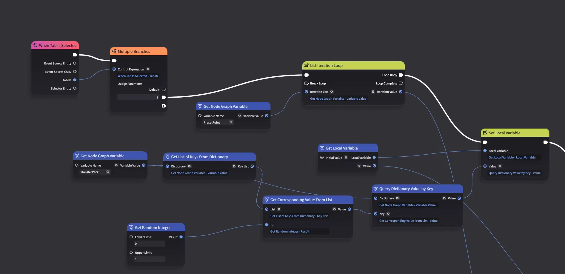
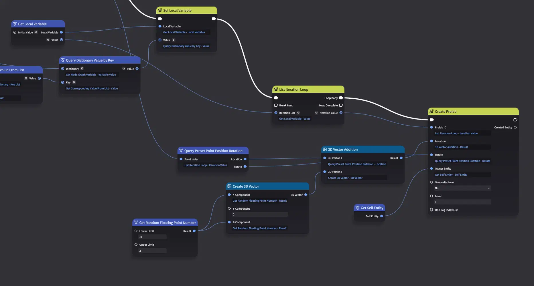
Next, iterate through the selected enemy group.
Here, we generate a random X/Y offset to prevent the enemies from spawning at exactly the same position. Alternatively, you can set up predefined offsets based on each enemy’s position in the group.
Then, create the enemies using their Component IDs.
2.1.3 Testing
Next, let’s enter the game and test what we’ve built so far.
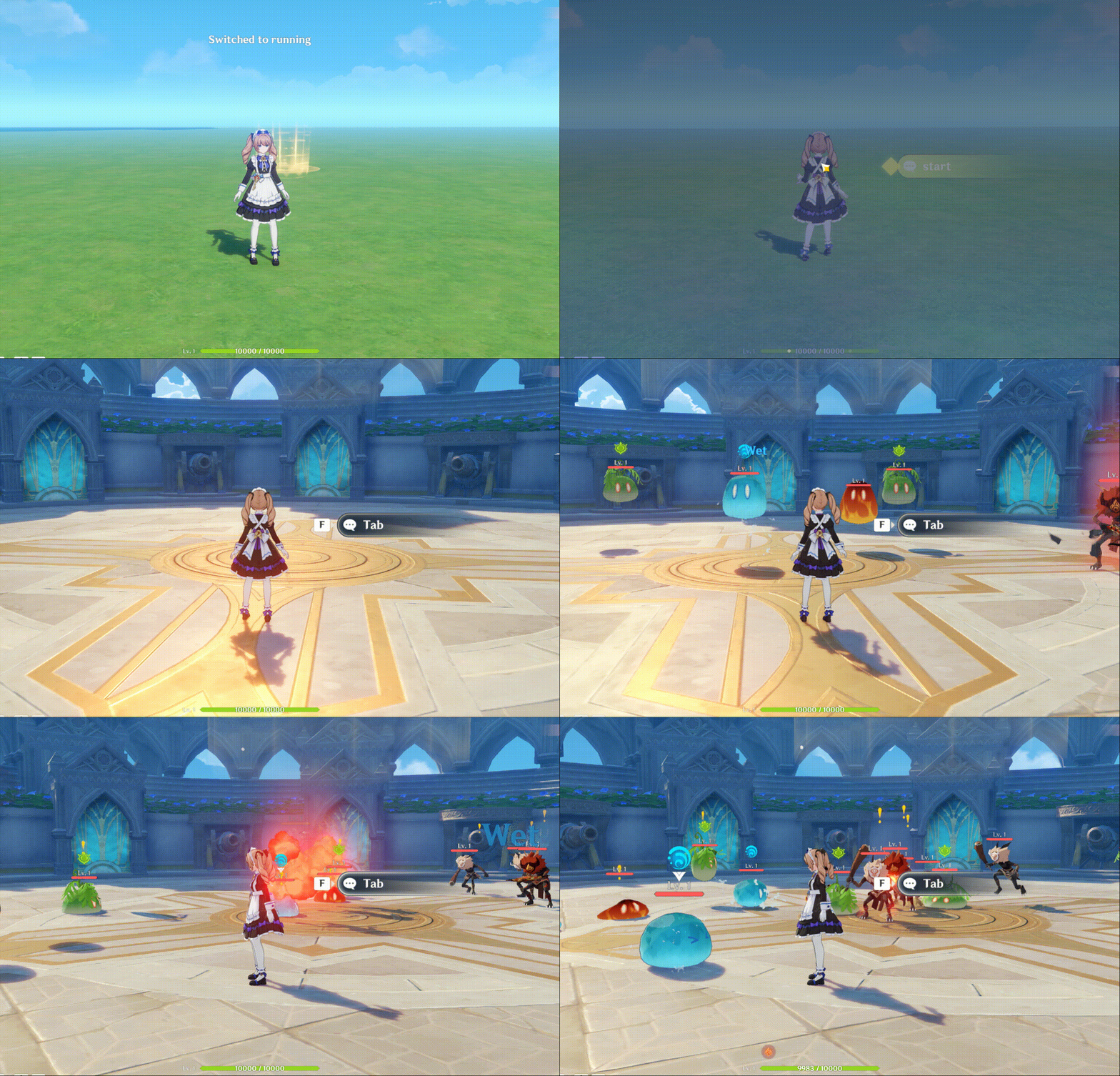
As you can see, each time we activate the Tab Component, a random group of enemies is spawned, exactly as expected.
2.1.4 Hiding the Tab Component
The feature is now working correctly, but you may have noticed one issue during testing~
The Tab Component doesn’t disappear. Normally, once combat begins, it should automatically be hidden. In Miliastra Wonderland, this behavior is handled through a Client Filter Node Graph.
Here, we’ll introduce the concept of a player state. For example, the player might be in the hub area, inside the arena, or currently in combat. We can assign each of these states a unique, mutually exclusive value, making it easy to determine the player’s current state.
So, add an integer variable named status to the player.
We’ll use different values to represent different player states.
For now, we’ll define them as follows: 0 for the default state, 1 for being in the arena, and 2 for being in combat.
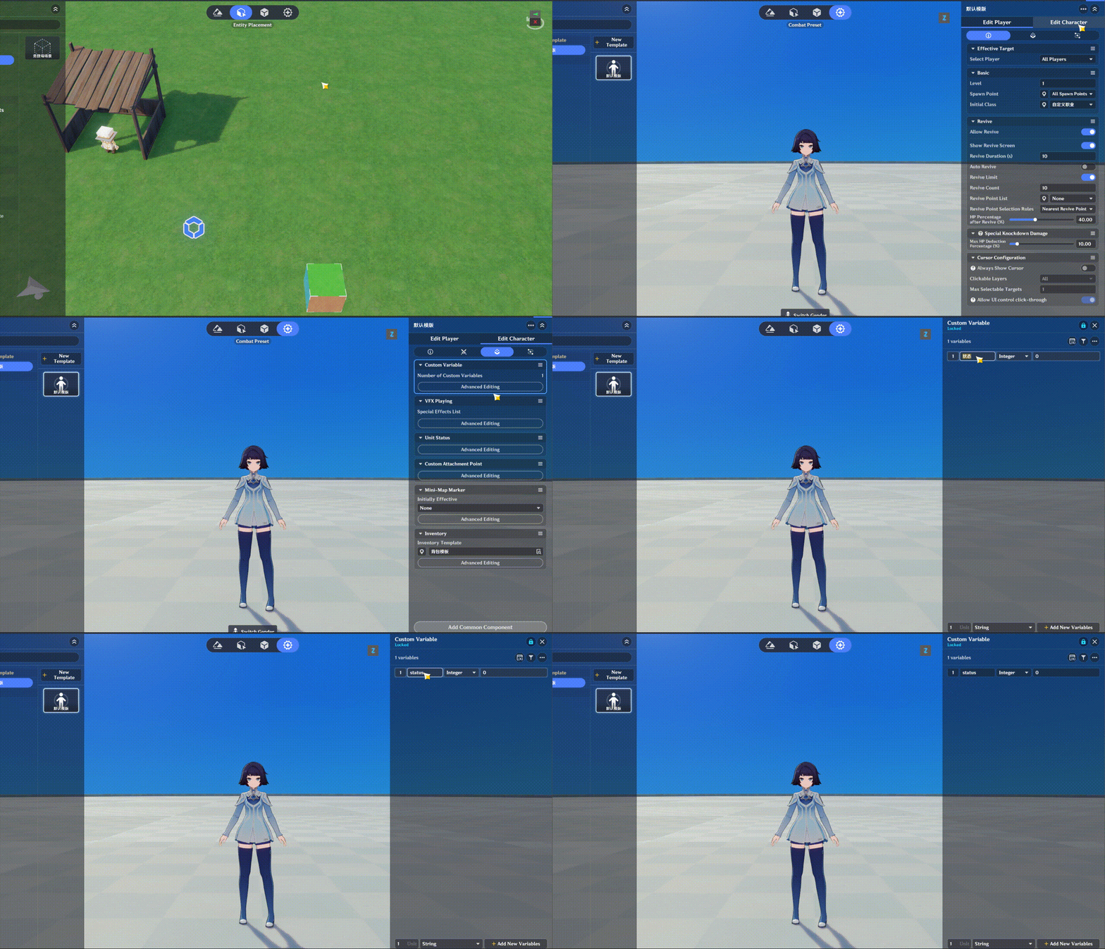
With this setup, we can simply hide the Tab Component whenever status is equal to 2, making it easy to achieve the behavior we want.
Now, open the Miliastra Sandbox and create a Boolean Filter.
Then, assign it to the Tab Component.
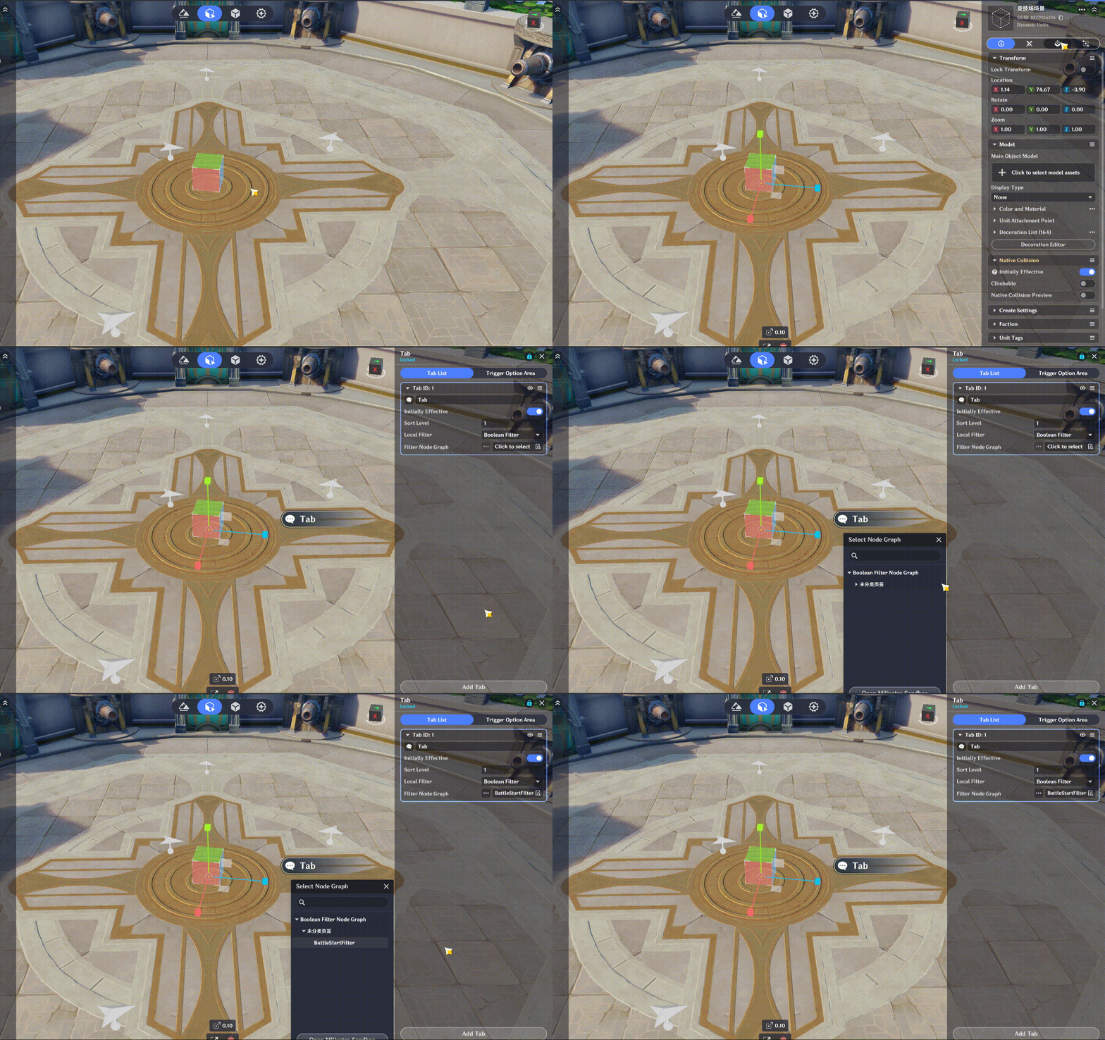
Next, let’s set up the Node Graph.
In the filter, the Target Entity refers to the player entity currently being evaluated.
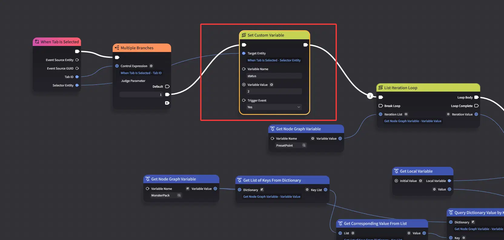
So, we simply check whether status is not equal to 2. If it isn’t, the filter outputs true, which means the Tab Component will be displayed.
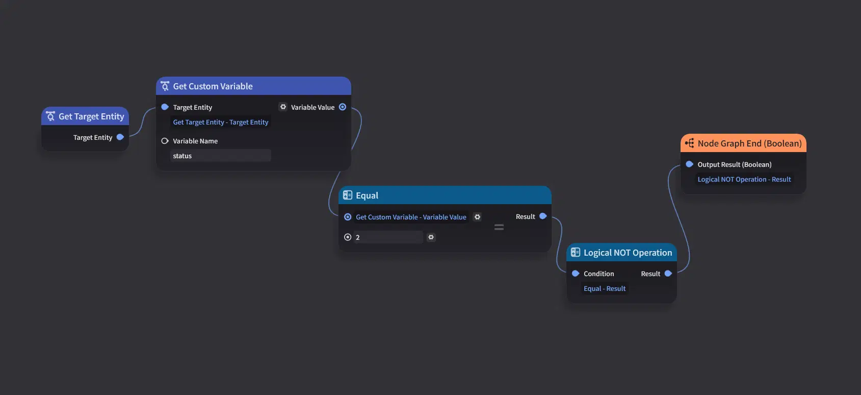
There’s one more change we need to make: once the Tab Component is activated and the enemies spawn, the player should enter the combat state.
So, after the Tab Component is activated, set the player’s status to 2.
All right, save the changes. Now it’s time to test it!
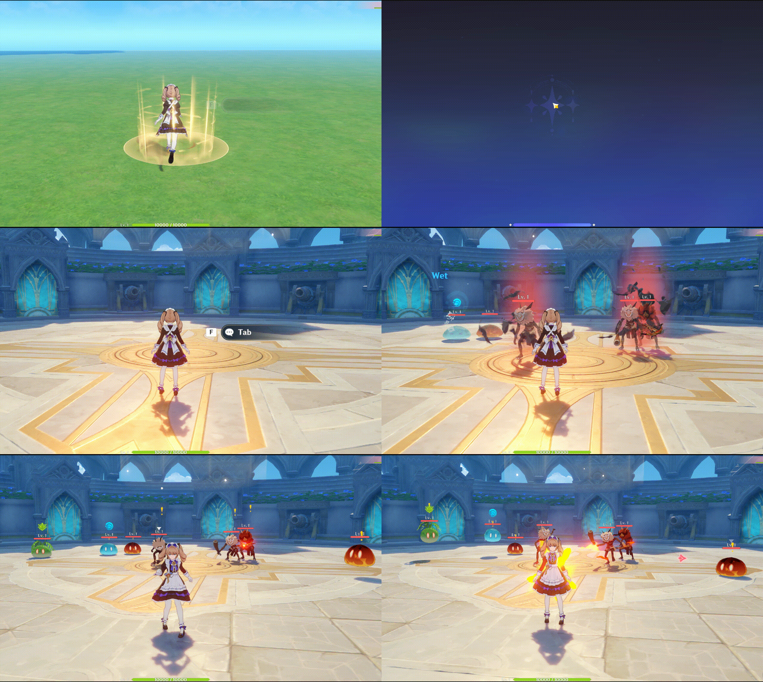
Once combat begins, the Tab Component is hidden, exactly as expected!
2.2 Kill Tracking and Floors
In this section, we’ll track kills for each floor. Once there are no enemies remaining on the field, the Floor count will increase by one.
2.2.1 Entity Ownership and Event Forwarding
You may have noticed that when we were setting up the Node Graph earlier, we connected an Owner Entity parameter.
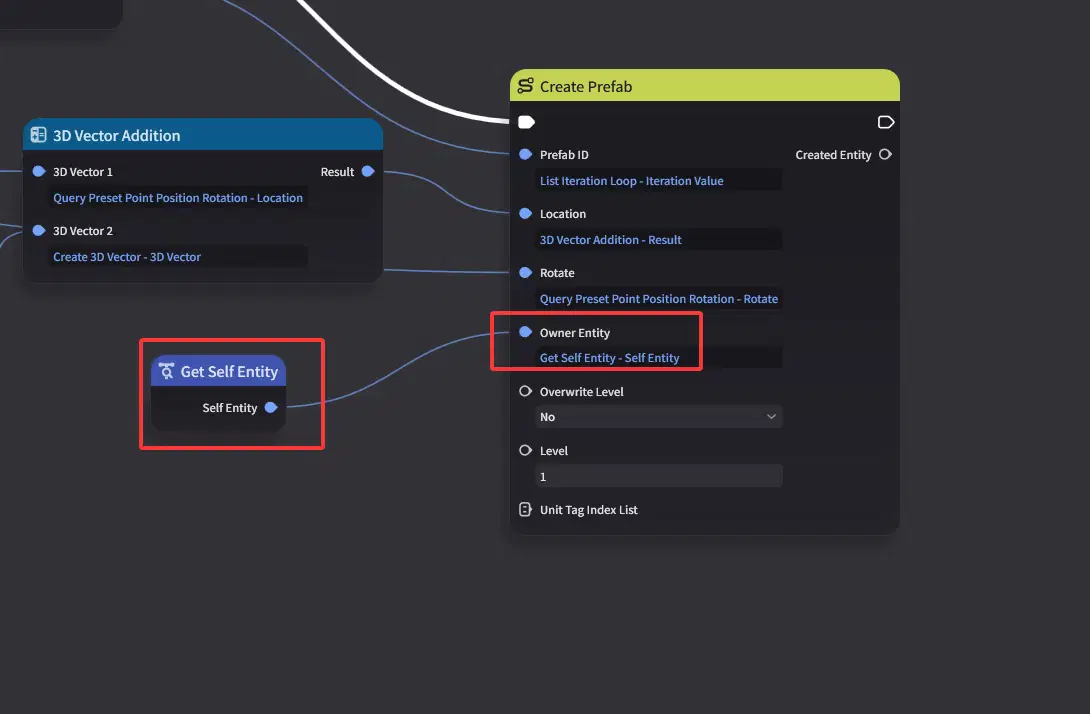
Here, we connected the Self Entity, which in this case is the arena. This means that the spawned enemy belongs to the arena.
So, what is this useful for?
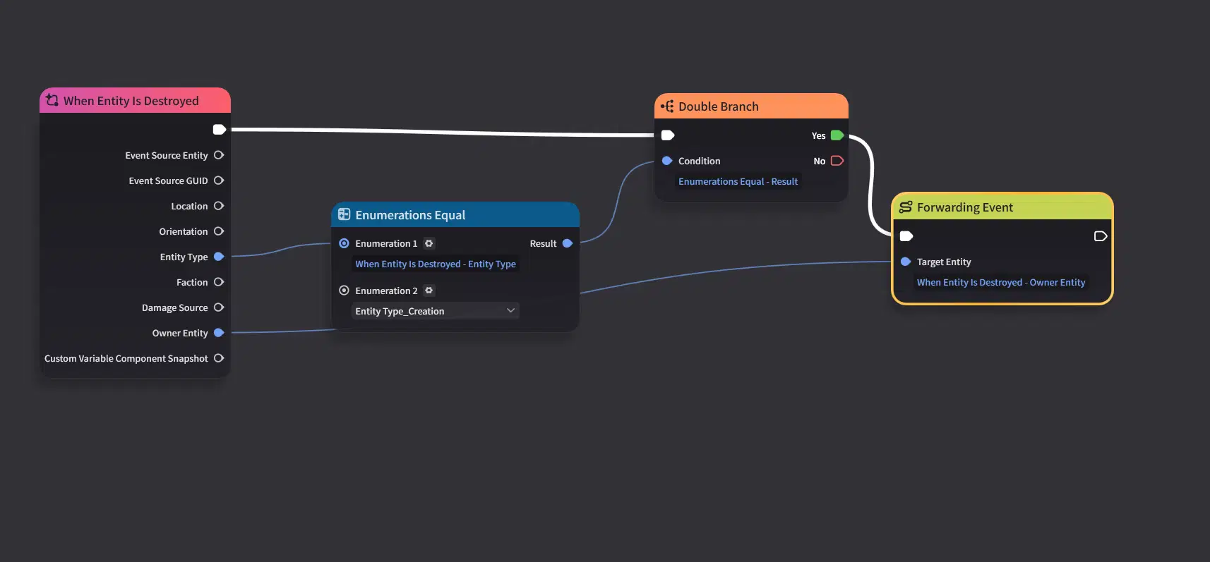
The Entity Destroyed event includes an Owner Entity parameter. This allows us to determine where the destroyed entity came from.
This may not make much of a difference in our current example, since all enemies come from a single source. However, once multiple scenes or multiplayer gameplay are introduced, using the Owner Entity becomes essential.
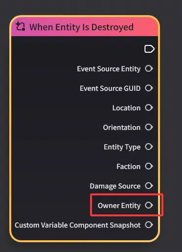
Of course, simply knowing where the entity came from isn’t enough. Here, we need to use another node in the Miliastra Sandbox: Event Forwarding.
This node allows an event to be forwarded to another entity for handling. In the Miliastra Sandbox, the Entity Destroyed event can only be received by the Stage. Following the principle of “whoever creates it should handle it,” we need to forward the event to the enemy’s Owner Entity.
If we handled everything on the Stage Entity instead, retrieving the required data would be more cumbersome, and the logic would become increasingly difficult to maintain as the Stage grows more complex.
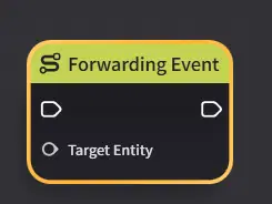
So, the overall flow should now be clear: set the Owner Entity when creating an enemy, then forward the event to its Owner Entity when the enemy is destroyed.
2.2.2 Editing the Node Graph
Now, create a Node Graph and bind it to the Stage.
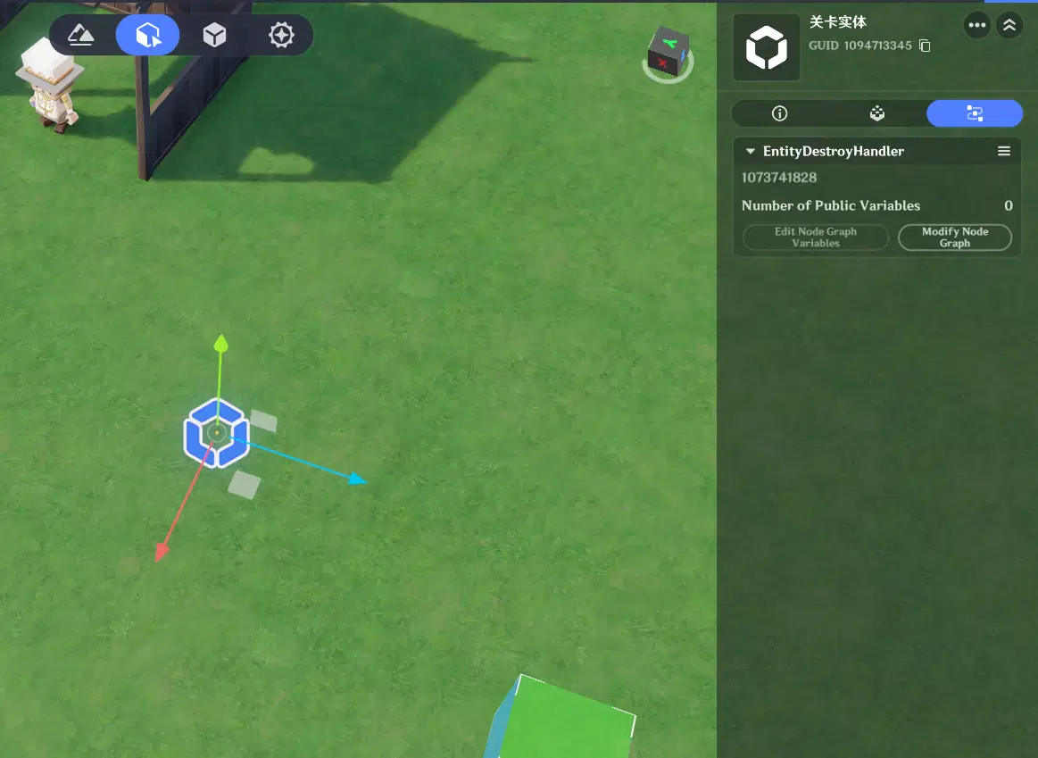
Next, let’s edit the Node Graph.
This Node Graph is fairly simple. First, check whether the destroyed entity is a Creation. If it is, forward the event.
Now, return to the arena Node Graph.
To keep track of the Floor count, total number of enemies, and remaining enemies, we need to create three Node Graph variables:
- Floor
- Total Enemies
- Remaining Enemies
Note that we’ll set the initial value of Floor to 1, since the Floor count starts from 1.
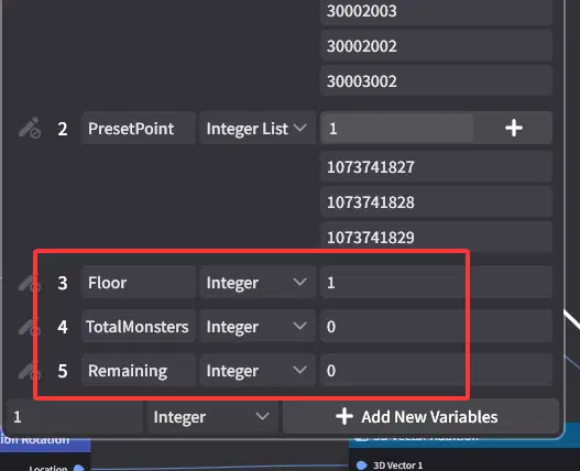
Tracking these values is very simple. Just increment Total Enemies by 1 each time an enemy is created. Once all enemies have been created, set Remaining Enemies equal to Total Enemies.
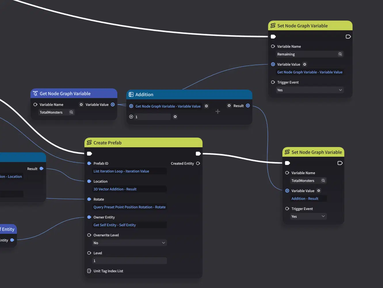
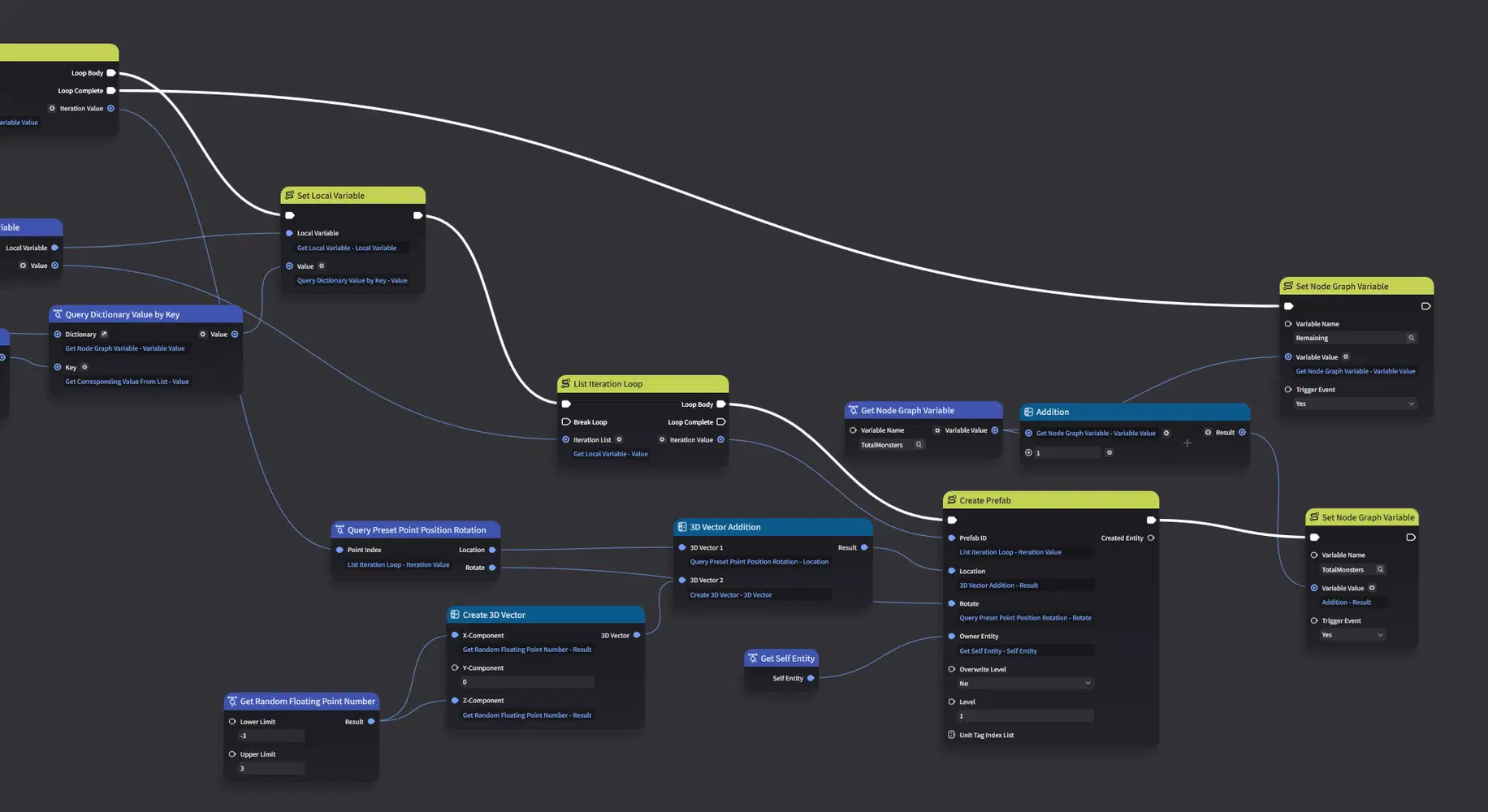
Next, let’s handle the enemy destruction logic.
Thanks to the event forwarding we set up earlier, the arena can now receive destruction events from the enemies it owns.
Each time an enemy is destroyed, decrease Remaining Enemies by 1. Once Remaining Enemies reaches 0, it means all enemies on the current Floor have been defeated.
Then, increase Floor by 1.
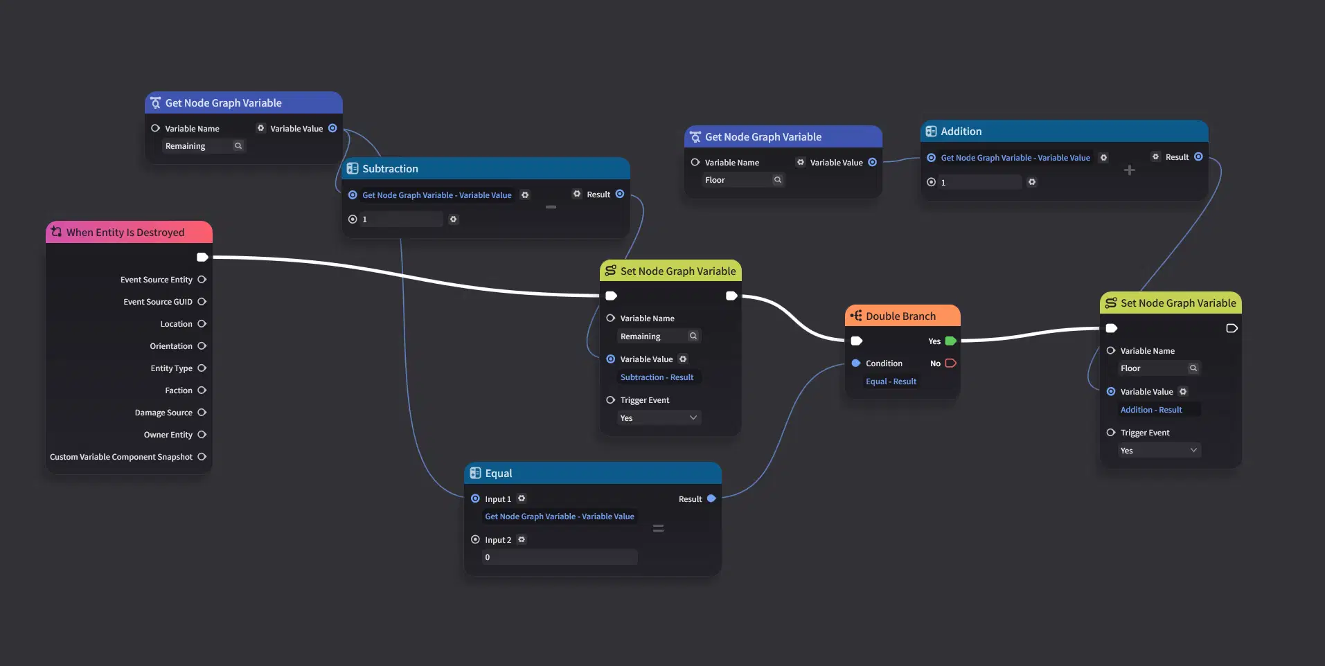
And don’t forget to update the player’s state so that the Tab Component becomes visible again.
We also need to reset Total Enemies to 0 to prevent enemies from being counted more than once.
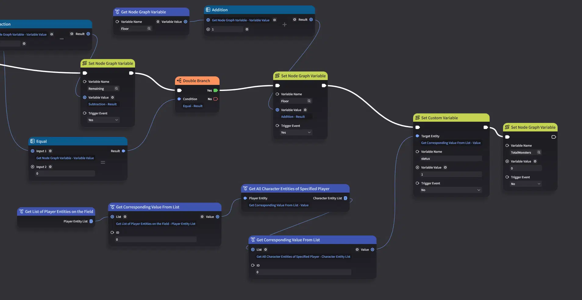
Next, let’s run a quick test!
Don’t forget to give the player the ability to attack, or you won’t be able to clear the first Floor.
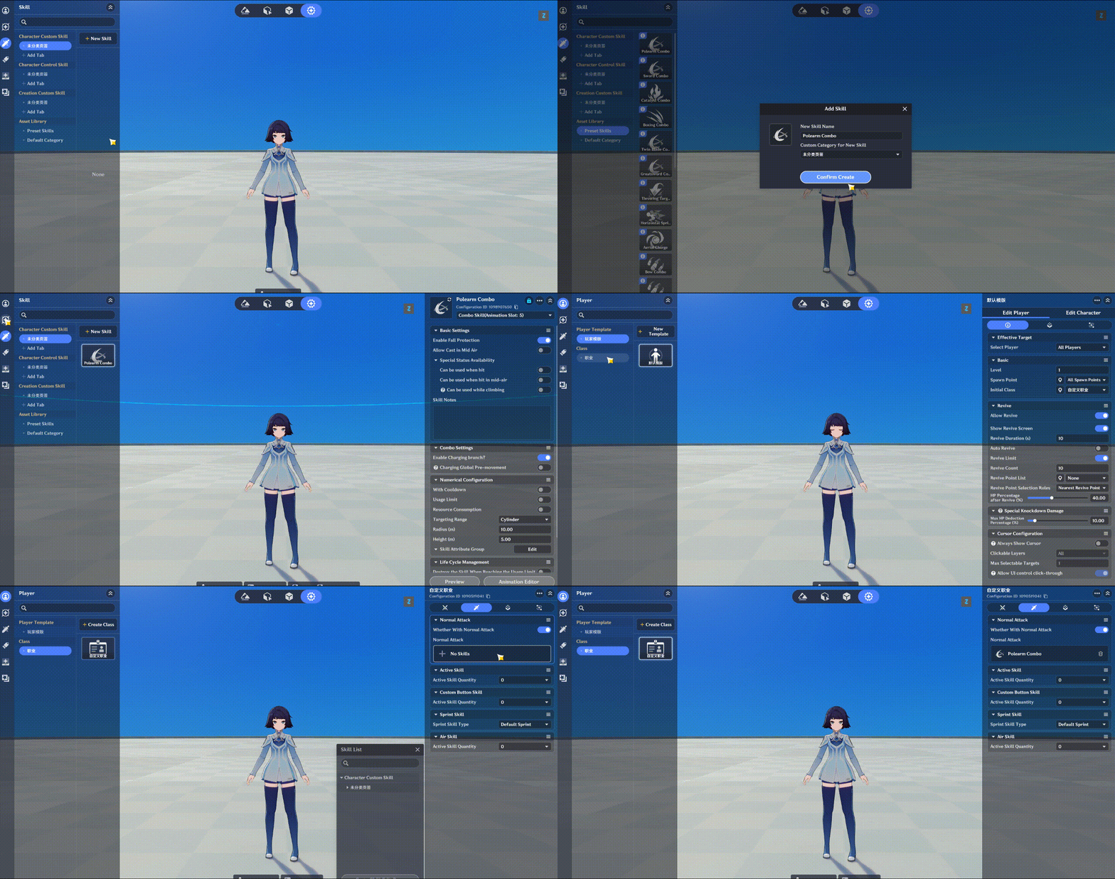
Check the test results. After all enemies are defeated, the Tab Component should appear again.
2.2.3 Simple UI
Obviously, relying solely on the Tab Component to tell whether the Floor has been cleared isn’t ideal.
Next, we’ll create a simple UI to display this information.
First, create a Struct for the UI.
Its structure should match the variables in the Node Graph.
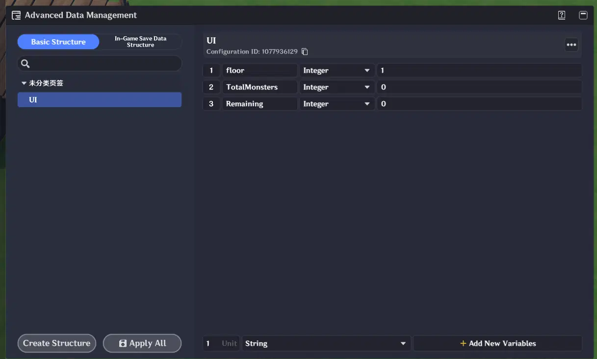
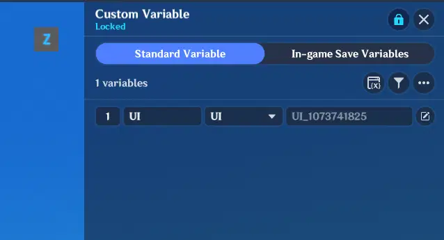
Create a new variable under Player Custom Variables.
Create a Text Box and place it at the top of the screen with a simple layout.
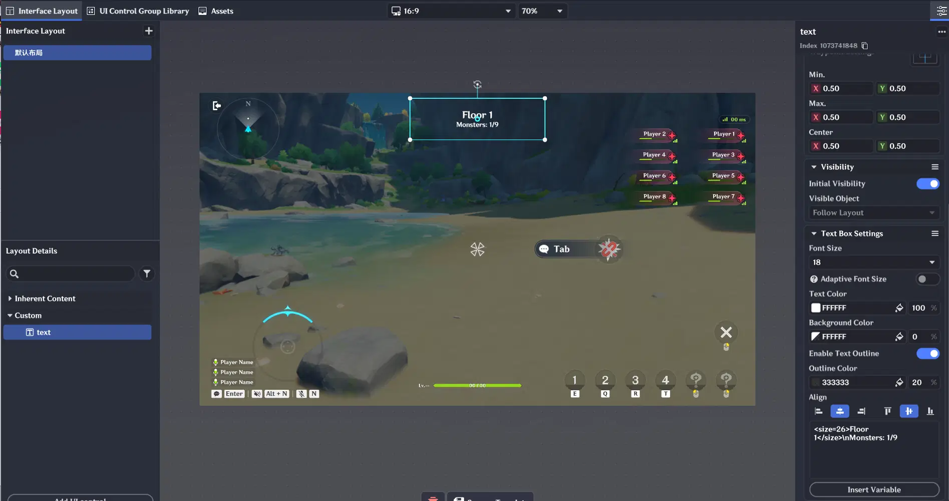
Bind the variables to the Text Box.
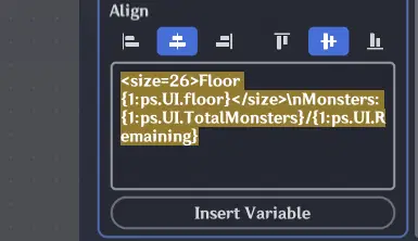
Return to the Node Graph.
Since all three values are integers, we can use a very simple approach.
Whenever a Node Graph variable changes, update the corresponding player UI variable based on which variable was changed.
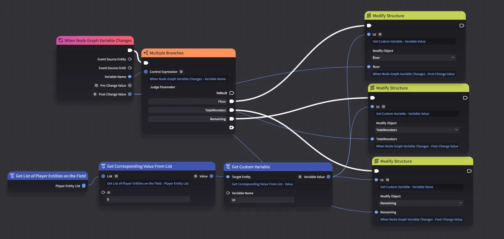
Let’s test it again!
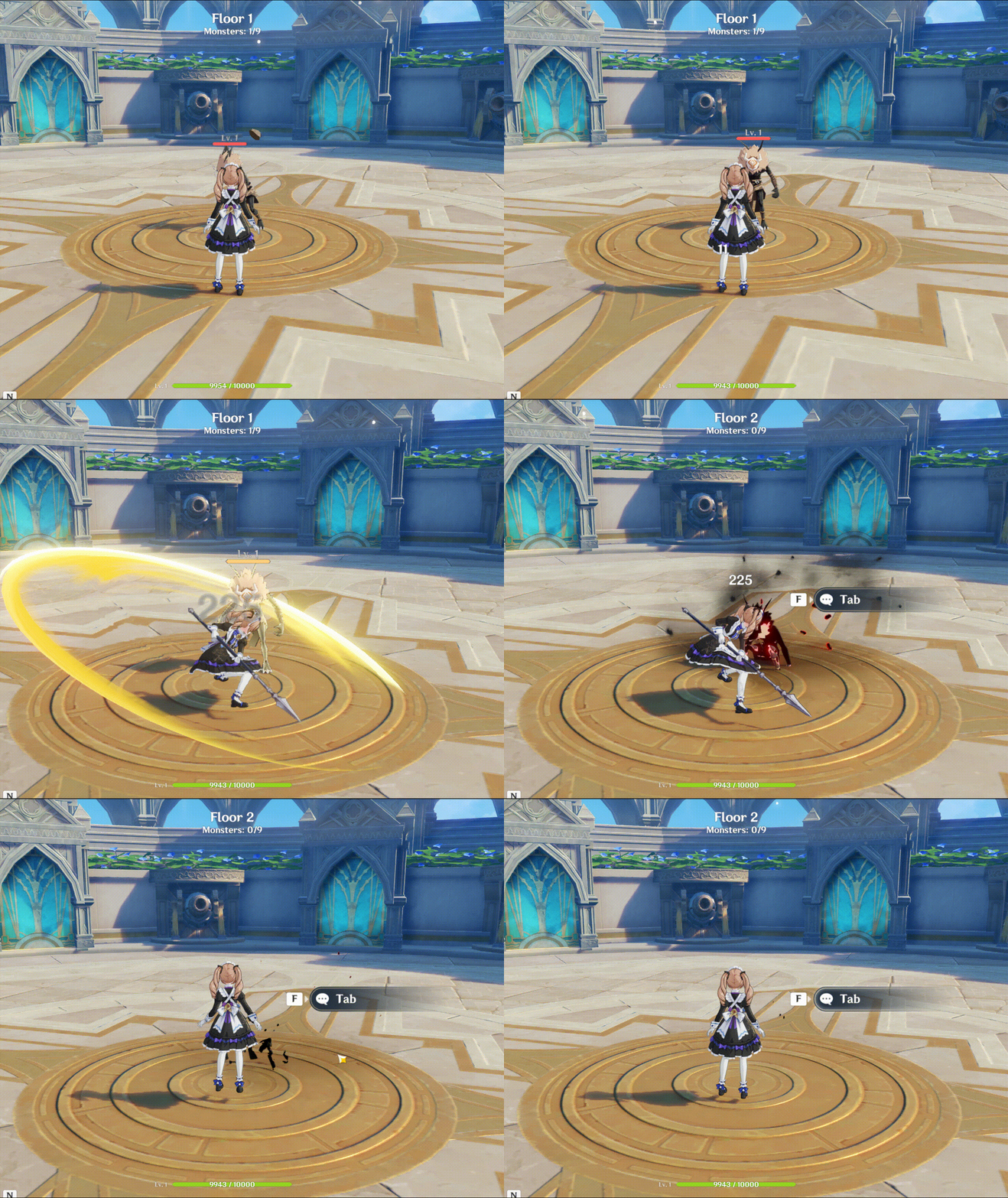
As you can see, once all enemies are defeated, the Floor count increases by one and the Tab Component reappears.
More updates coming soon~~
3. Basic Buffs and Card Selection
For a roguelike game, simply clearing one Floor after another isn’t enough. After each clear, the player should receive a reward.
In this section, we’ll first create several basic buffs and go through the full process of card selection → reward granting → effect activation.
To make the stat increases easier to observe, we’ll also create a simple stats panel.
Let’s get started!
3.1 Stats Panel
We’ll continue using a minimal layout here. In your own game, you can polish the presentation and make it look much better!
3.1.1 Creating the Basic UI
Next, open the UI Control Groups page and create a Text Box.
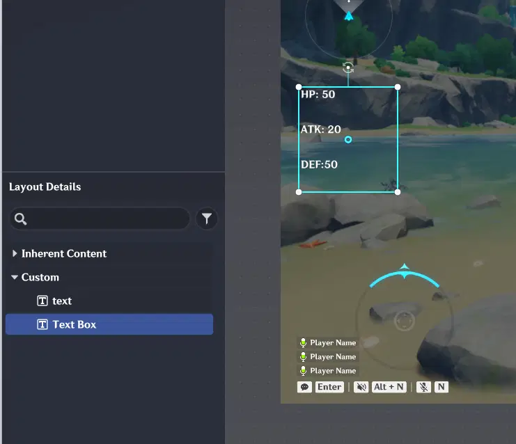
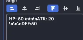
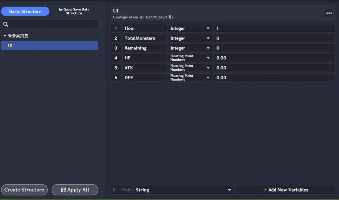
Next, add these three stats to the UI Struct.
For displaying stats, you can use either floating-point values or integers. Floating-point values are more precise, while integers usually provide a cleaner visual presentation.
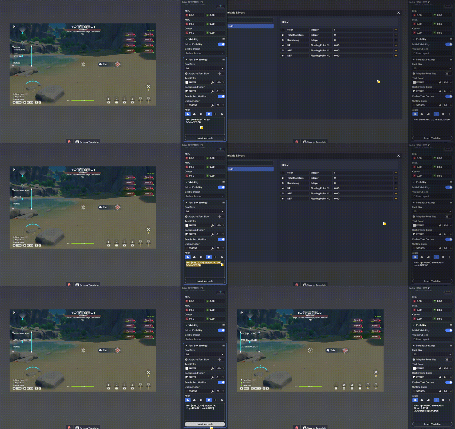
Return to the UI editor and bind these values to the Text Box.
3.1.2 Refreshing UI Stats with Signals
We want stat updates to be responsive, while also avoiding unnecessary refreshes.
So, we’ll use a passive update approach: the UI will only refresh when it receives a refresh signal. Any system that changes the player’s stats only needs to send that signal.
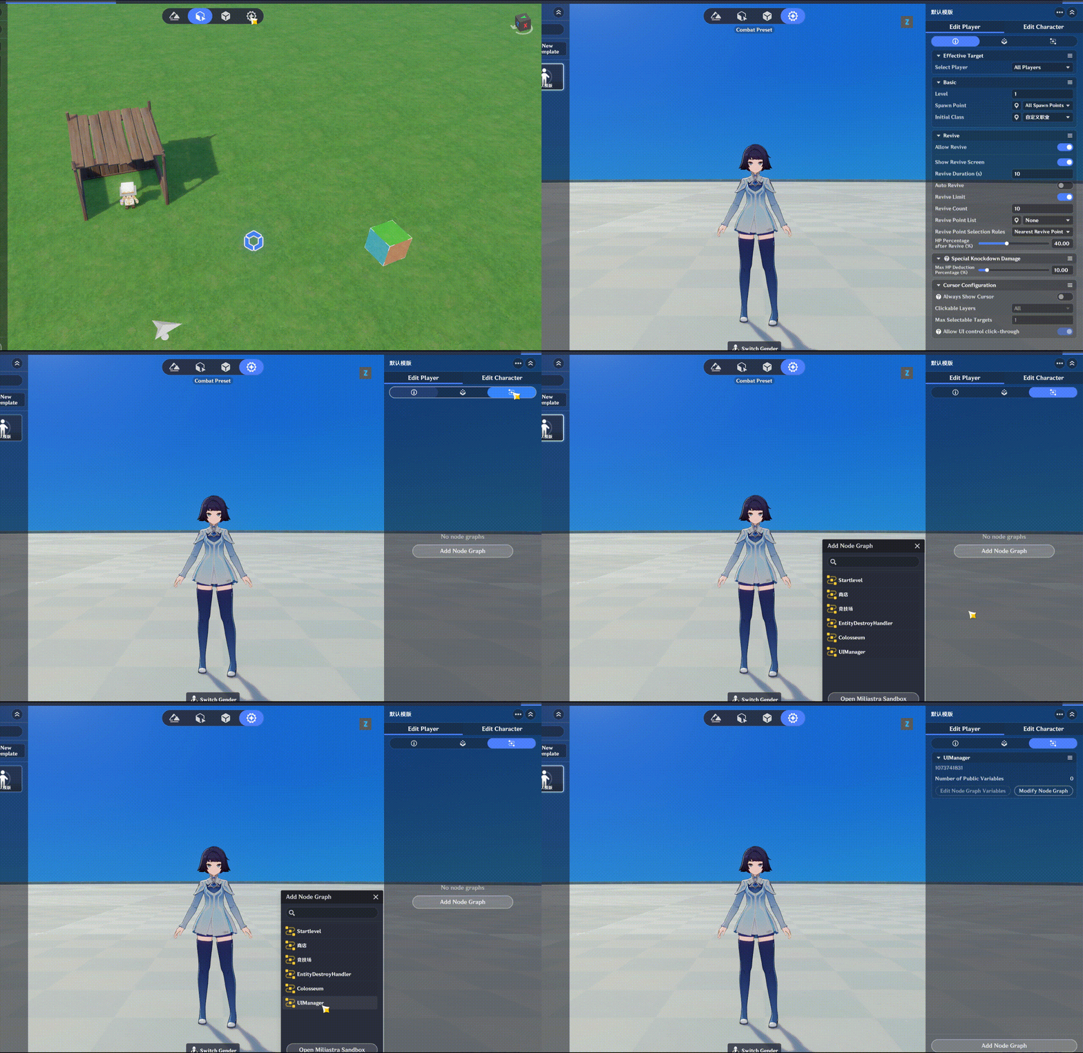
Go to the Node Graph editor, create a blank Node Graph named UI Manager, and bind it to the Player.
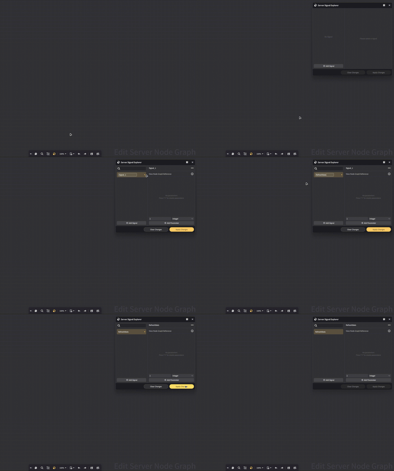
Go to the Node Graph and create a signal for refreshing the stats. Name it RefreshStats.
It doesn’t need any parameters, since it only serves as a notification that the UI should update.
Now, let’s assume we’ve already received the command to refresh the UI and start implementing the Node Graph.
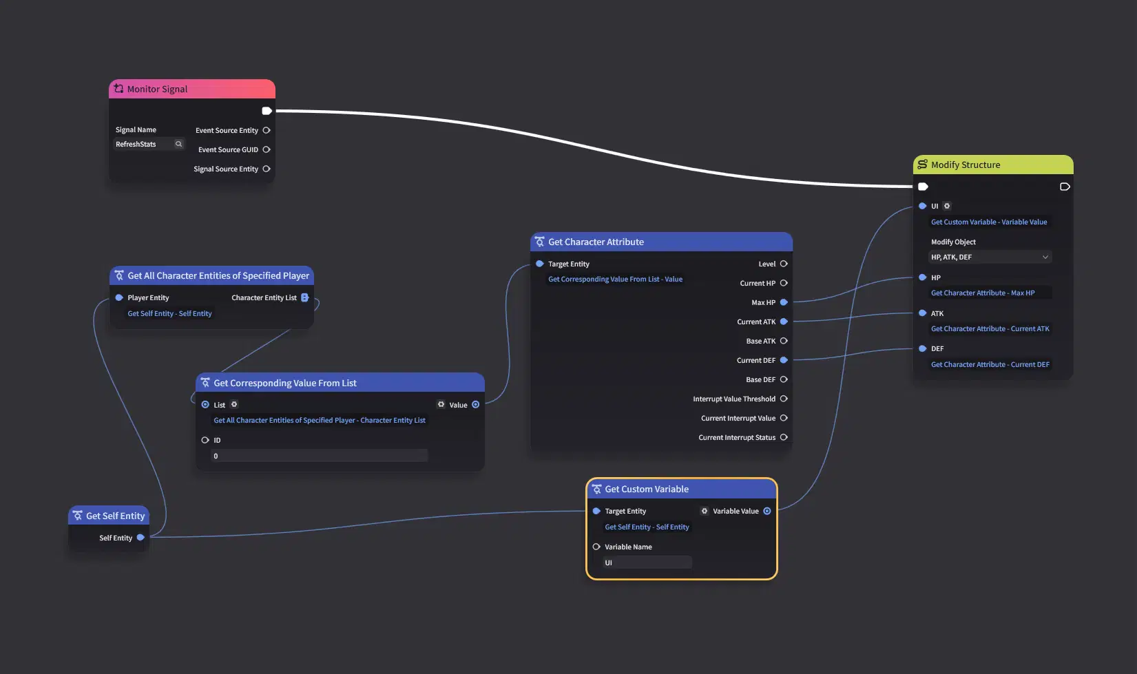
Begin with the signal event.
Get the player character’s stats, then update the corresponding values in the UI Struct.
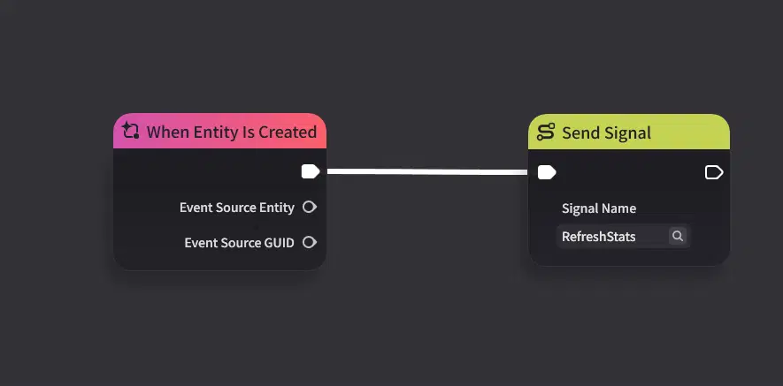
Next, add a signal that is sent when this Node Graph is created.
This ensures that the displayed stats are already up to date when the player enters the game.
Now, enter the game and test it!
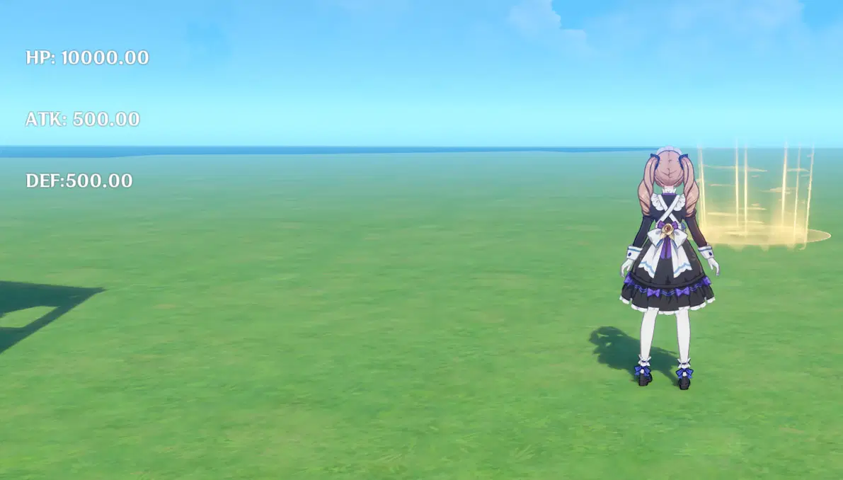
The stats are now displaying correctly!
3.2 Basic Buffs
Let’s start with the basics by creating a simple ATK buff.
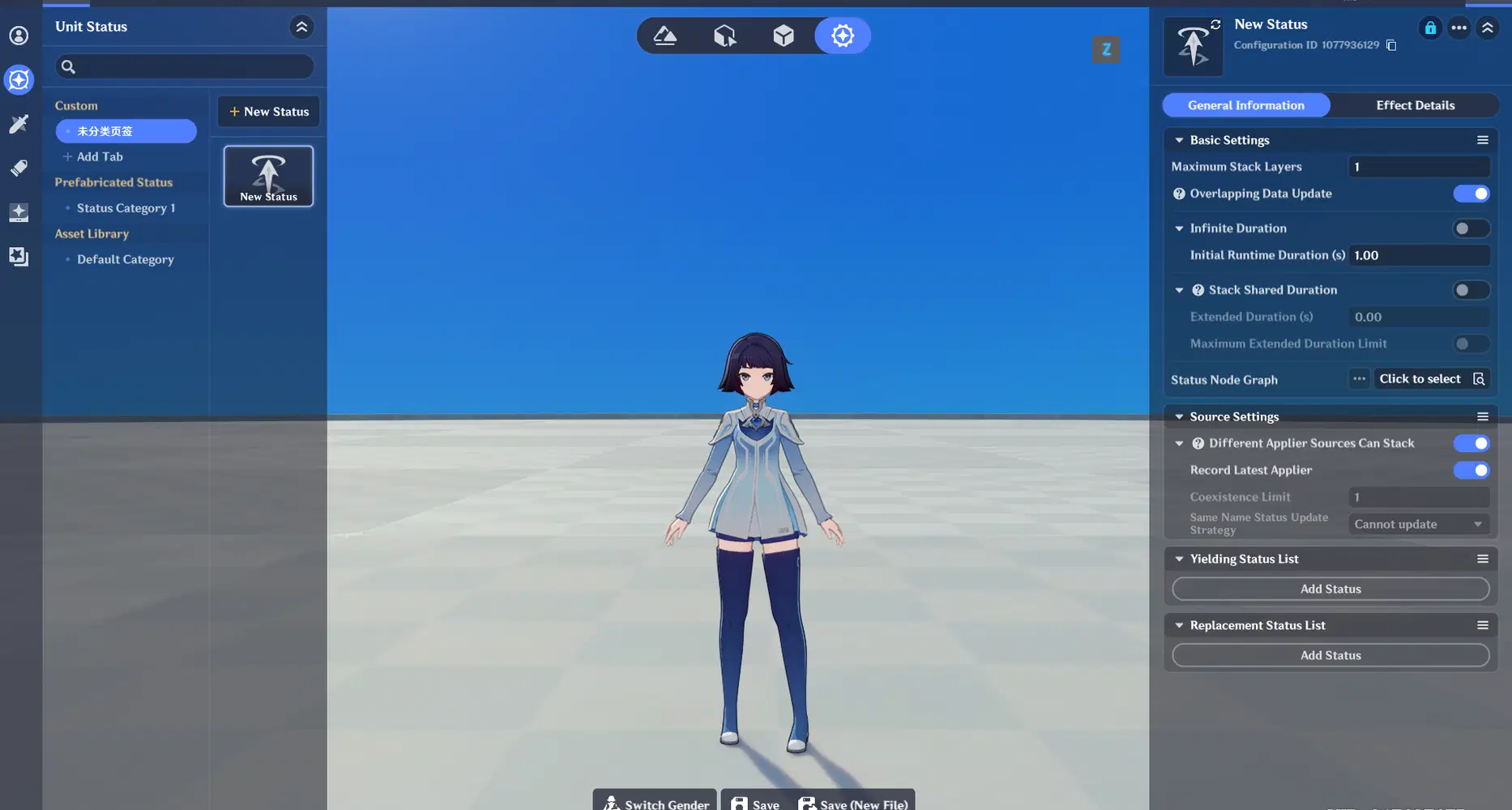
In Miliastra Wonderland, buffs like this are generally implemented using States, which provide a wide range of built-in features.
These include duration limits, stacking, coexistence, and replacement behavior.
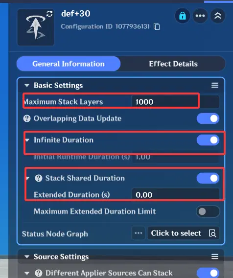
Since the buff we’re creating will be granted through cards, it should have an unlimited duration and also allow stacking. In the State settings, set the duration to Infinite and the maximum stack count to 1000.
Make sure to enable Stack Shared Duration. If it is disabled, the maximum stack count will be limited to 10.
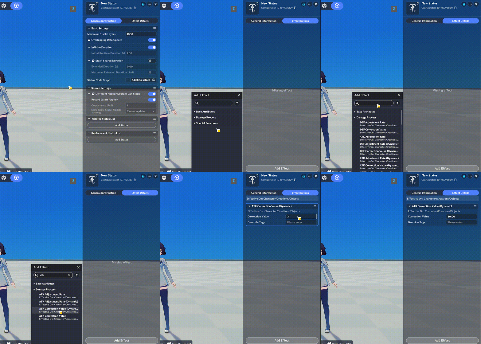
Next, add an ATK increase effect to this State. We’ll have it grant 30 ATK.
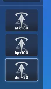
Using the same method, create corresponding buffs for HP and DEF. We won’t go through the process again here, but make sure you finish setting them up so that you have all three States ready.
Next, create a Torch and add three Tab Components to it. We’ll skip the basic setup process here.
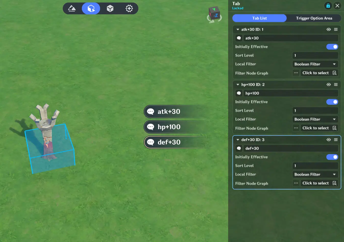
Create a Node Graph and bind it to the Torch, then add a Multi-Branch node.
For each Tab Component, apply the corresponding State you created earlier.
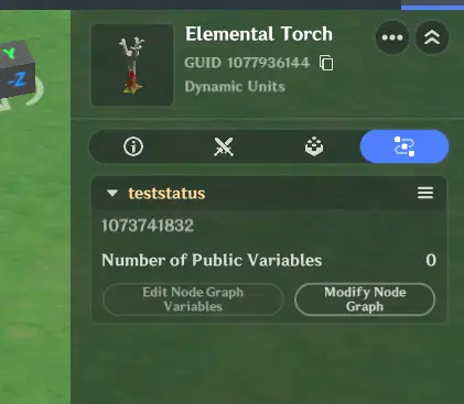
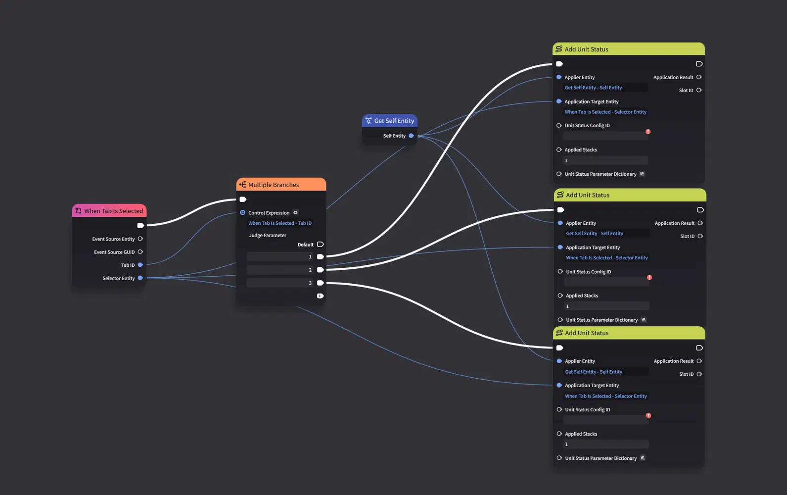
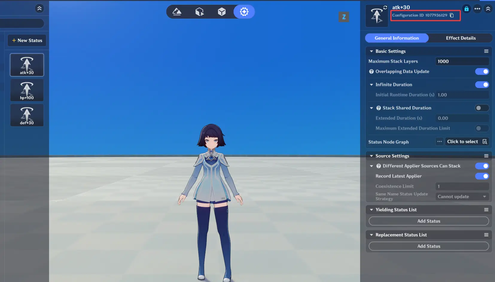
Check the State IDs here, then enter each corresponding ID into the Node Graph.
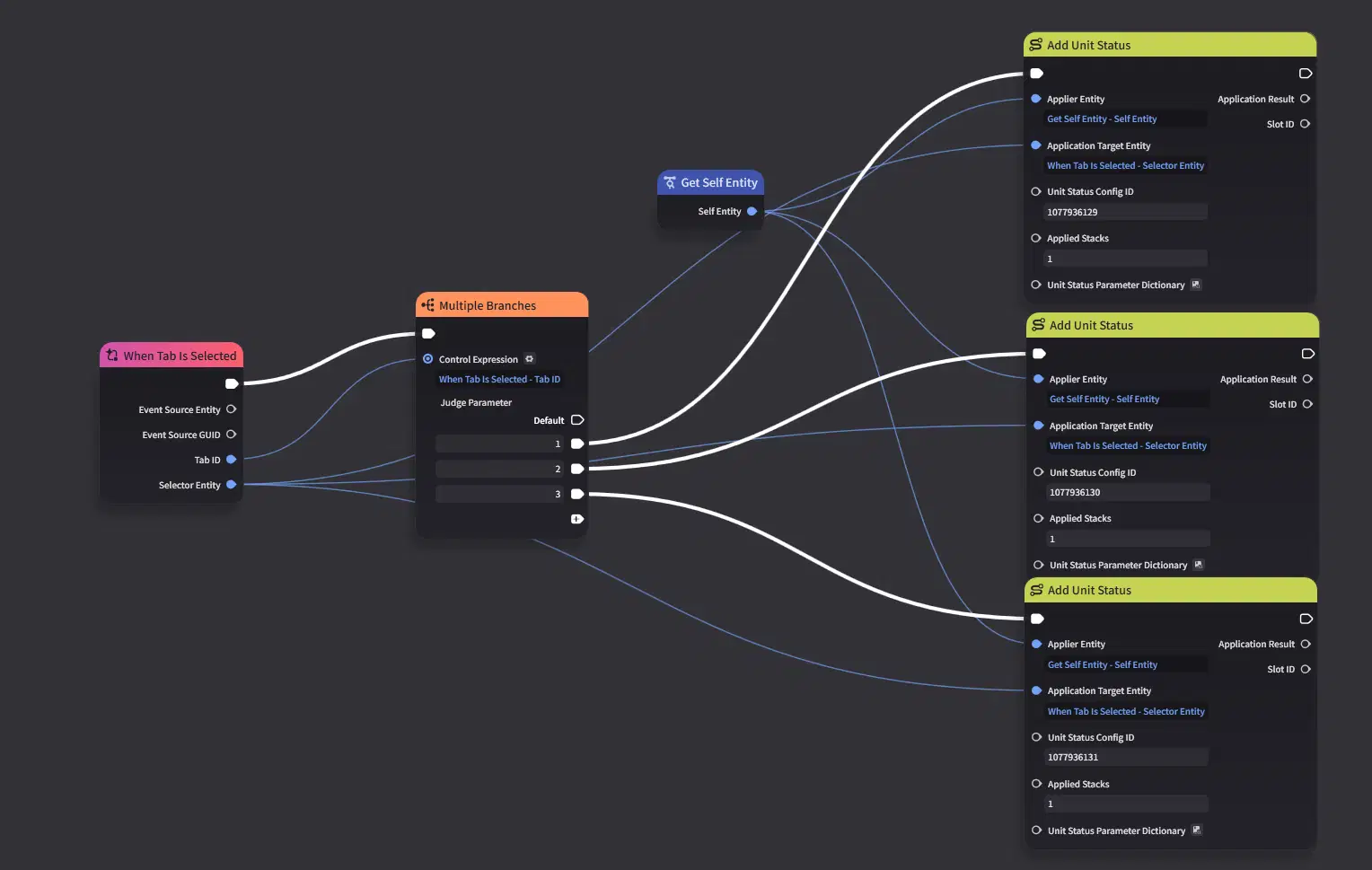
Remember the design we set up earlier? Whenever a stat changes, we should send a signal to refresh the UI.
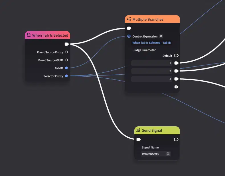
In a Node Graph, multiple connections are executed in the order they were connected. So we can simply attach the signal to the second connection. This ensures that the refresh signal will still be sent after execution, no matter how the first path is modified later.
Now, enter the game and continue testing the result!
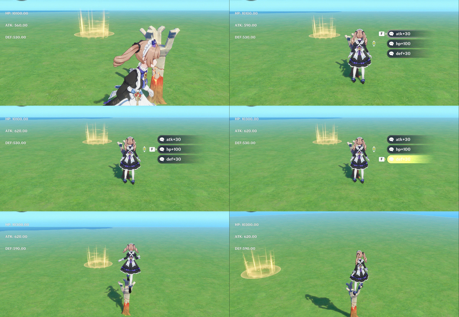
The stats panel and the buff effects are both working correctly!
3.3 Card Selector
As you can see from the previous test, increasing the player character’s stats is simply a matter of applying the corresponding State.
The Card Selector works in the same way: first determine which card the player selected, then apply the corresponding State to the player character.
That’s all we need to complete the buff flow!
Now, let’s head to the UI editor and start creating the Card Selector.
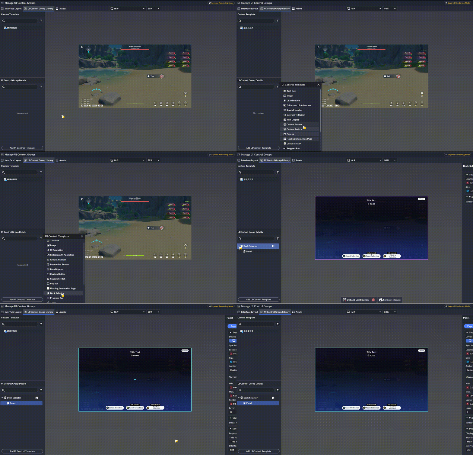
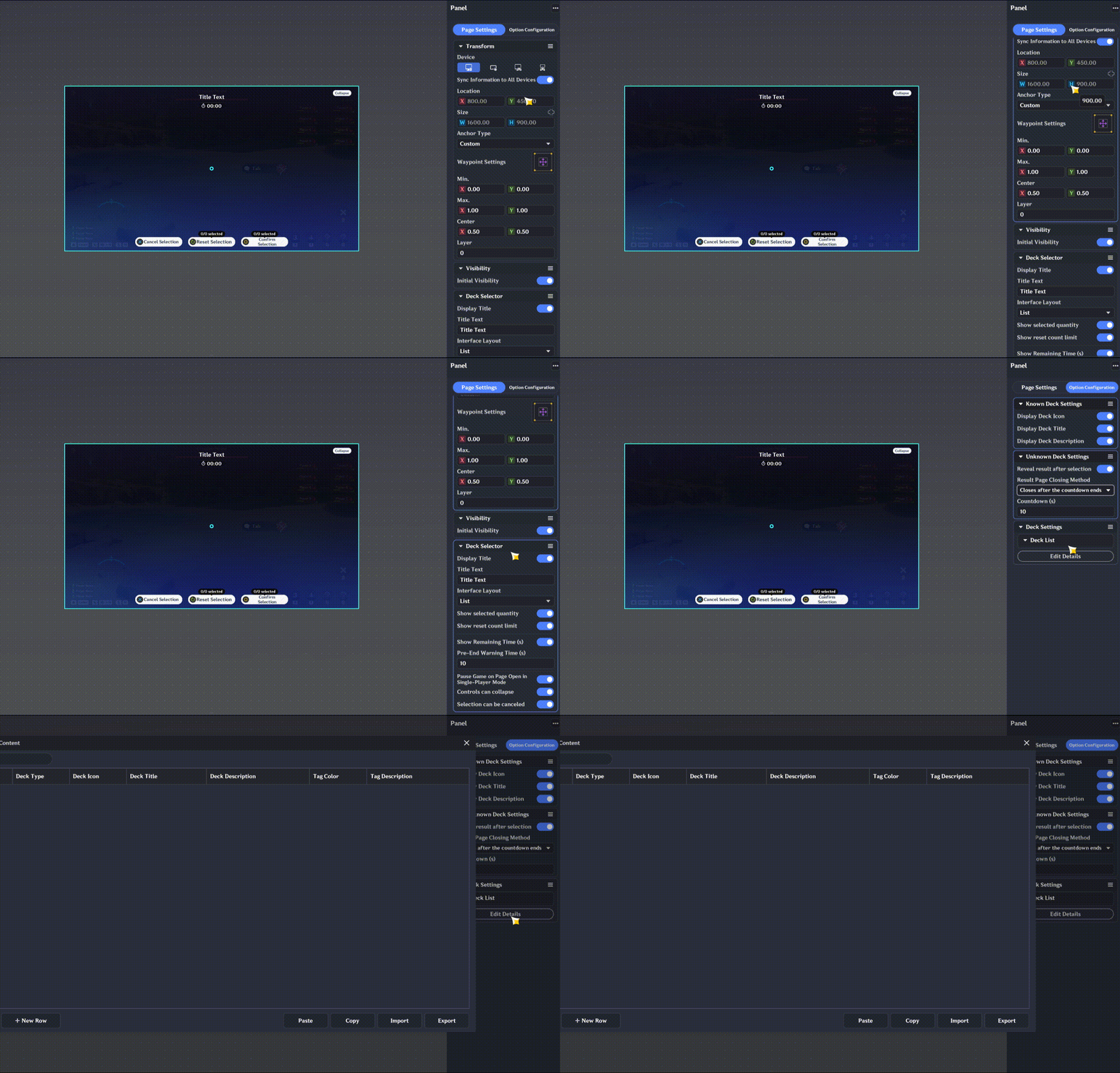
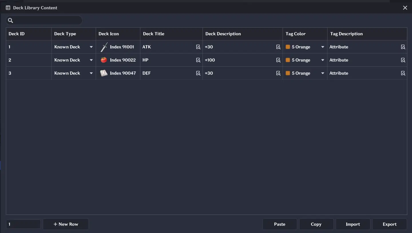
The card creation page actually works more like a card pool.
We need to prepare all the cards that may appear in advance, then use the Node Graph to determine which ones are actually displayed.
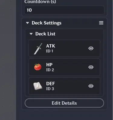
For now, let’s create three cards: HP, ATK, and DEF.
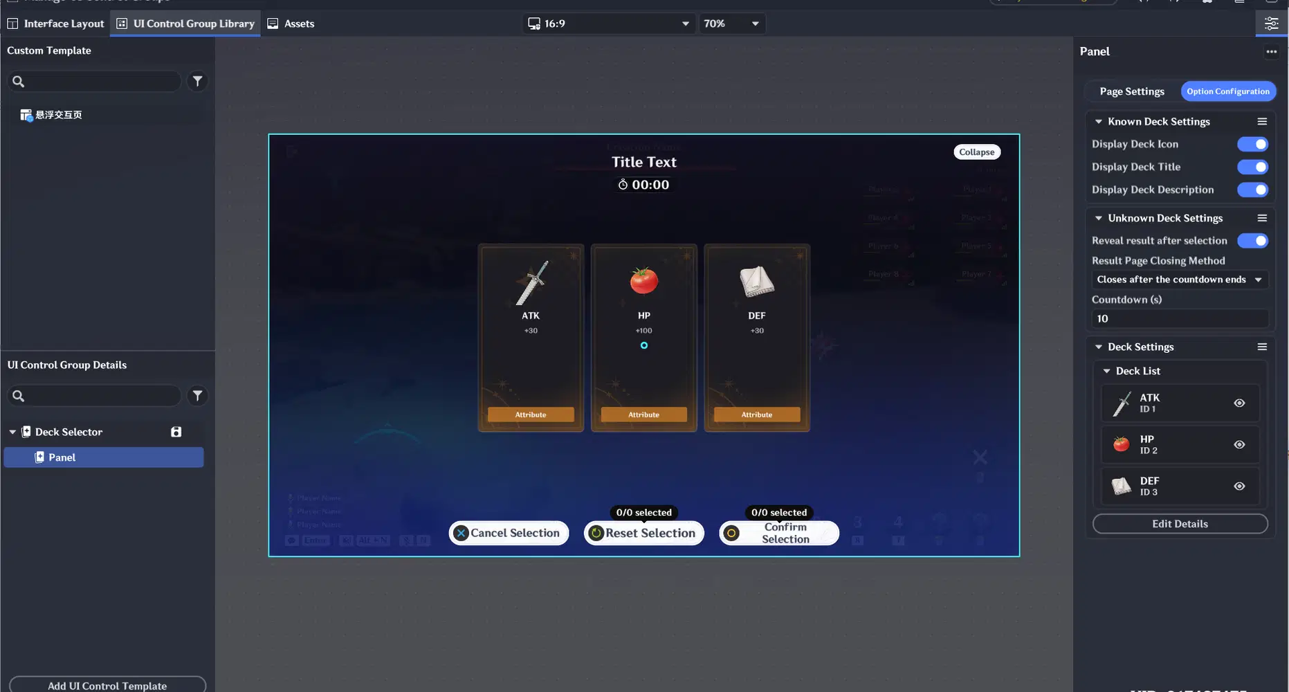
Next, save it as a template. The Card Selector must be opened through a Node Graph.
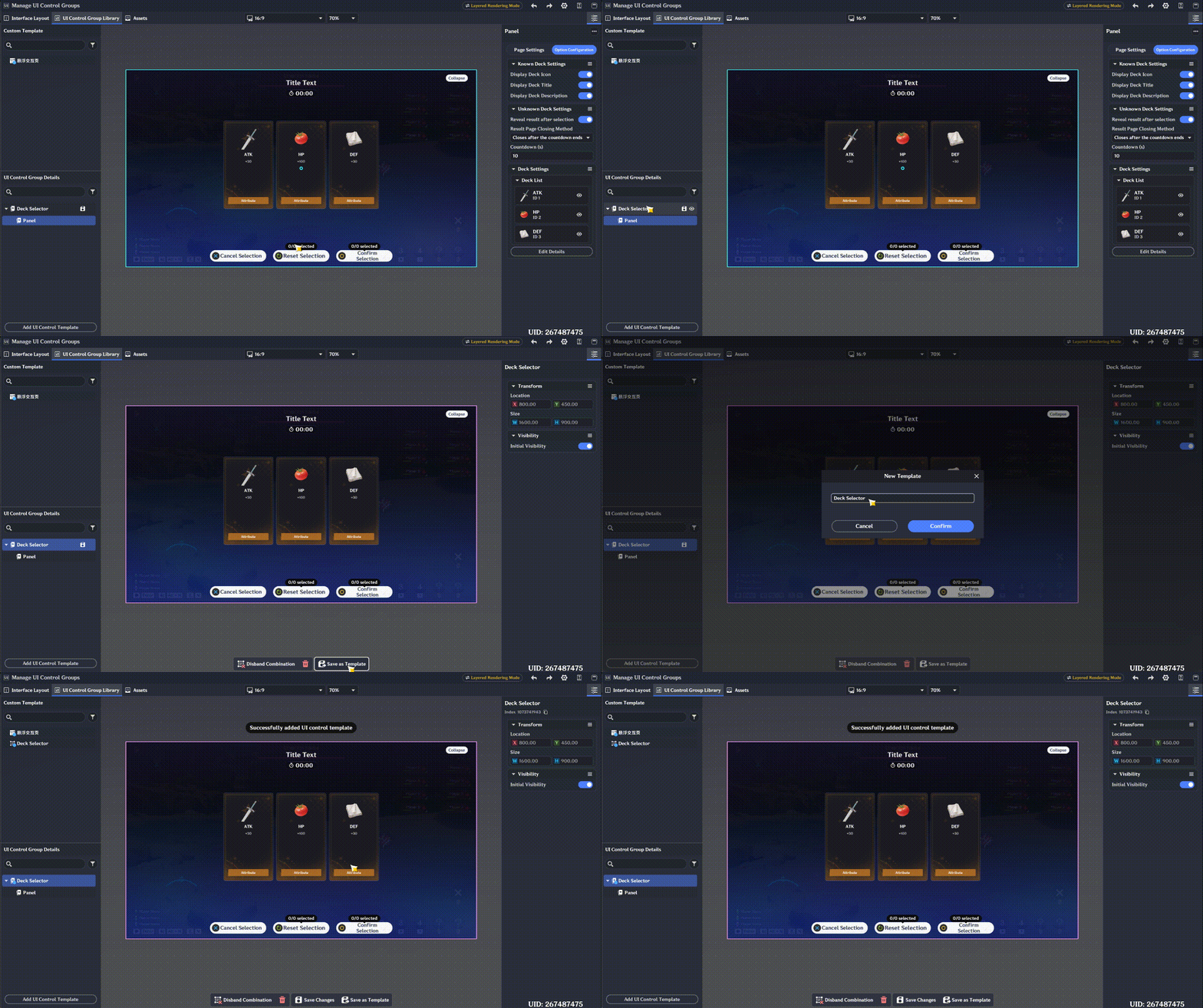
Node Graph Editing
Let’s first outline what we need to do so the Node Graph will be easier to follow:
Clear the Floor → Open the Card Selector and set the available cards → Process the player’s selection → Apply the corresponding State to the player character
Let’s go through it step by step~
Open the arena Node Graph.
At the end of the Floor-clear logic, add the function that opens the Card Selector.
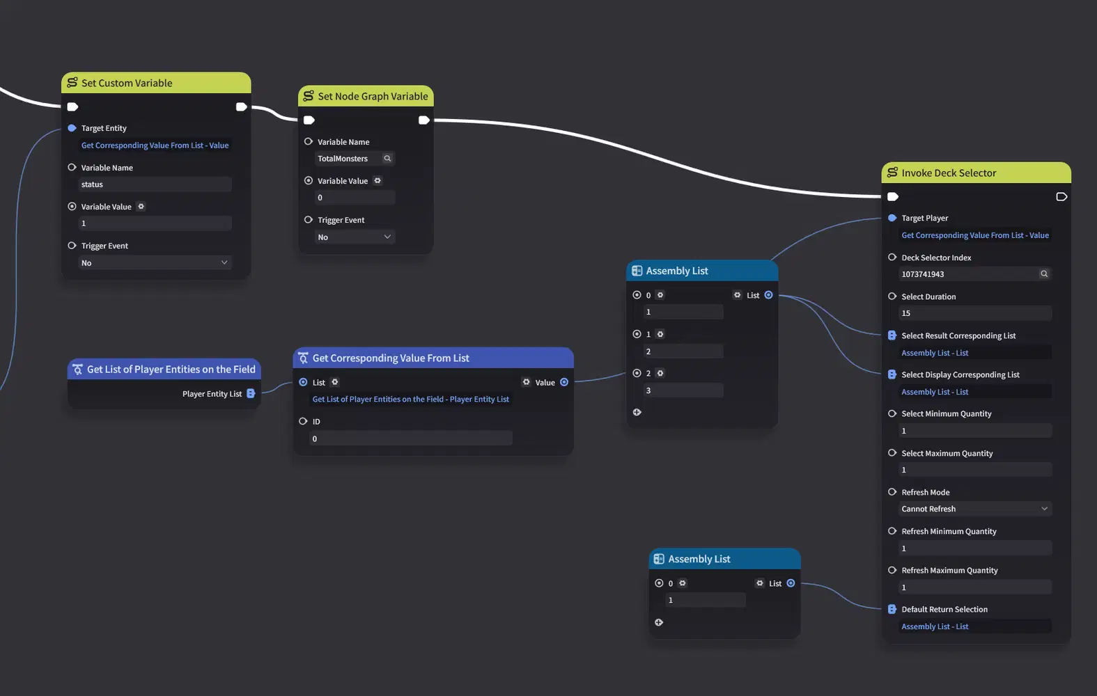
Let’s take a moment to explain these parameters. As mentioned earlier, the cards configured in the UI editor act more like a card pool, while the list you provide here determines which cards are actually displayed.
Each card we created earlier has its own ID. Add the corresponding IDs to the list to make those cards appear in the Card Selector.
Next, go to the player’s UI Manager Node Graph. Completing a card selection also triggers an event, and this event can only be received by the Player Entity.
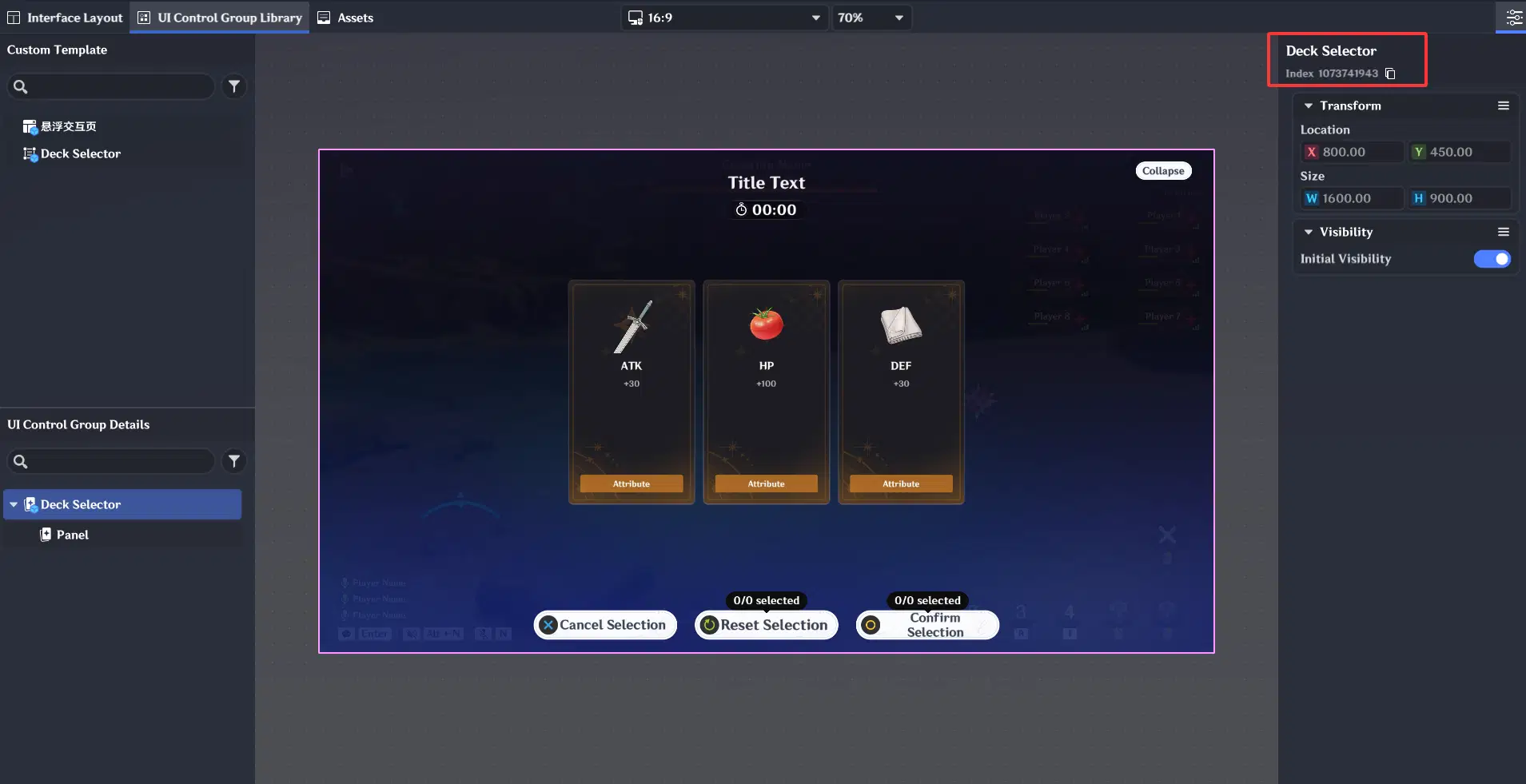
Here, we’ll once again avoid handling the logic directly. Following the same principle that “whoever creates it should handle it,” we’ll forward the event to the arena based on the Card Selector index.
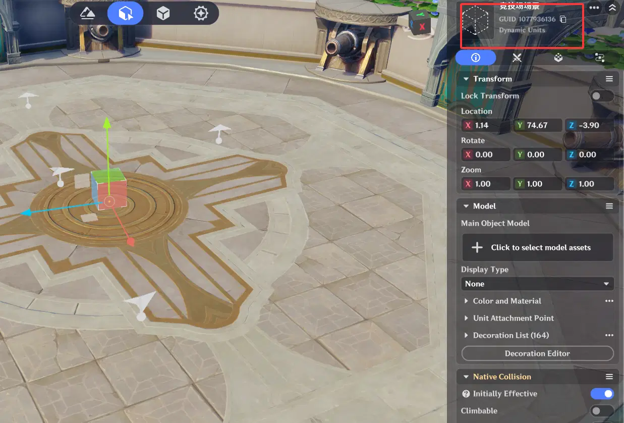
To reference the arena entity, we need to obtain it through its GUID. Go to the scene and copy the arena’s GUID.
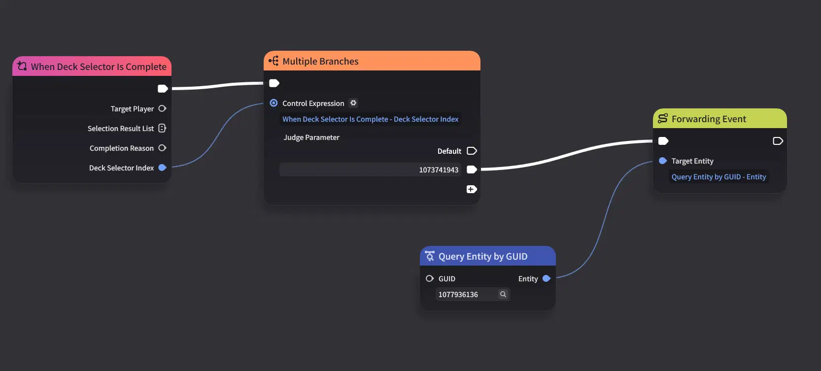
Then, return to the arena Node Graph and continue processing the event.
We can directly reuse the State test logic from earlier, since the indices 1, 2, and 3 correspond to the same three options.
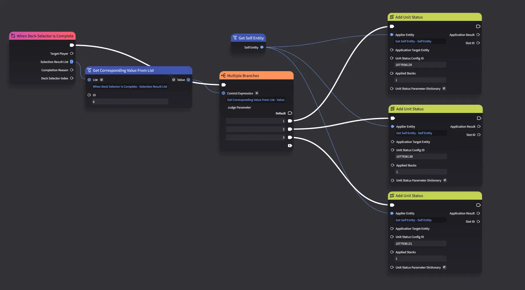
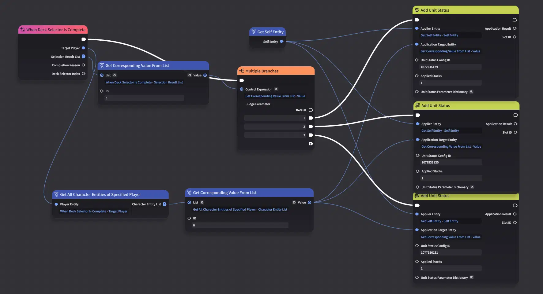
The selected entity is the Player, but the State needs to be applied to the player character.
So, we first need to get the player character entity.
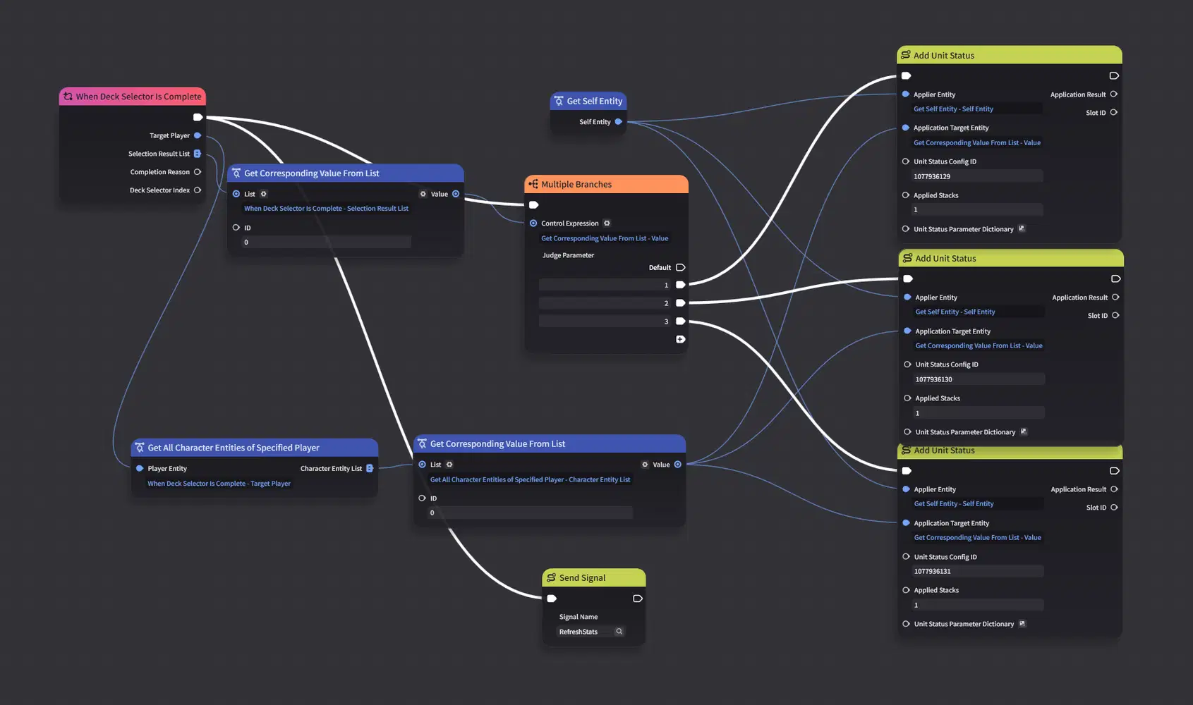
Don’t forget to refresh the UI.
All right, let’s continue with another test!
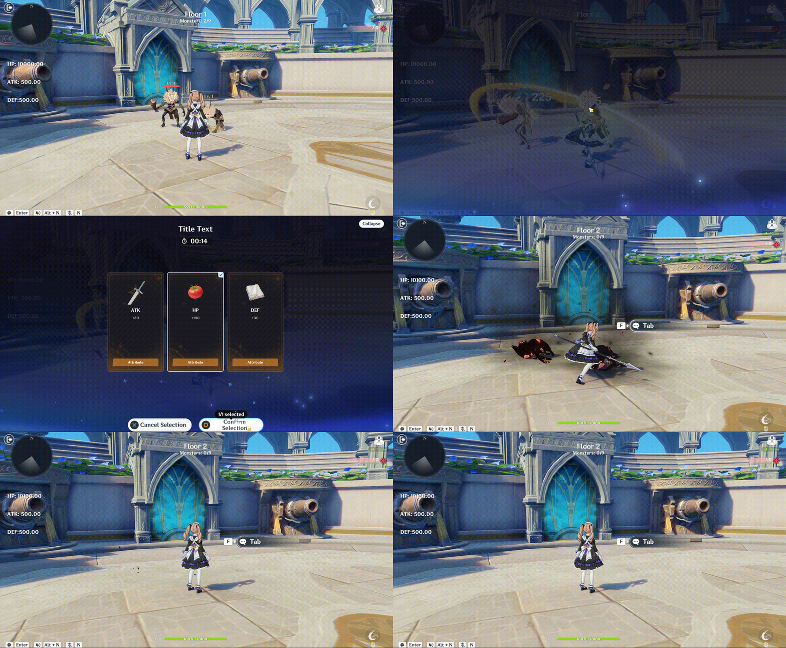
As you can see, the card effects are working correctly, and the UI is displaying the updated stats as expected.
阶段性存档,如果您需要可以在此下载
https://drive.google.com/file/d/1wRL5rMBbpzWKXIhl2rT5JQ3iUGGYBoID/view?usp=sharing
4. State Management and UI Visibility Control
As you may have noticed, in the current demo there is no way to leave the Stage once we enter it, and the UI remains permanently displayed on the screen.
Obviously, that won’t work. So in this section, we’ll implement three features:
- Track stat stack counts
- Control UI visibility based on state
- Clean up buff effects
Once these are complete, the basic framework of our game will be largely in place. From there, the remaining work will mainly focus on expanding the gameplay and systems—after all, things are still pretty bare-bones right now!
4.1 Basic UI Control
Controlling the UI will actually be quite simple. Remember the state management system we set up earlier?
That’s right—the basic UI display will follow the player’s current state.
We defined 1 and 2 as the Stage and Combat states, while 0 represents the default state.
So, whenever the state changes, we simply update the UI display accordingly. This gives us dynamic control over when the UI is shown or hidden.
4.1.1 Adding an Exit Tab Component
First, add an Exit Tab Component to the arena and configure its filter as well.
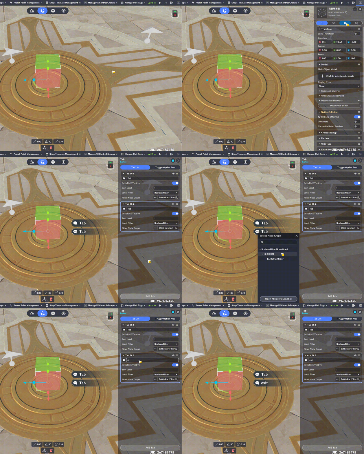
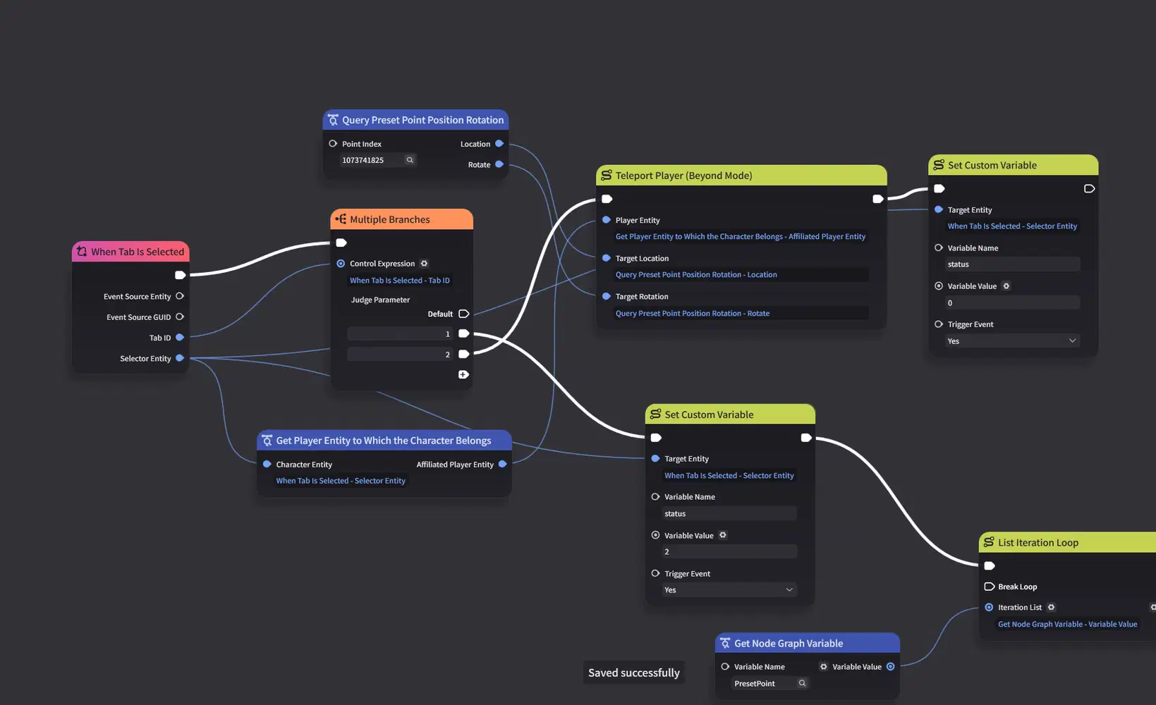
Continue editing the arena Node Graph.
For now, we only need to do two things here:
- Teleport the player back to the home area.
- Change the player’s state.
First, use the spawn Preset Point to get its position. This will be our teleport destination.
Now, enter the game and test it!
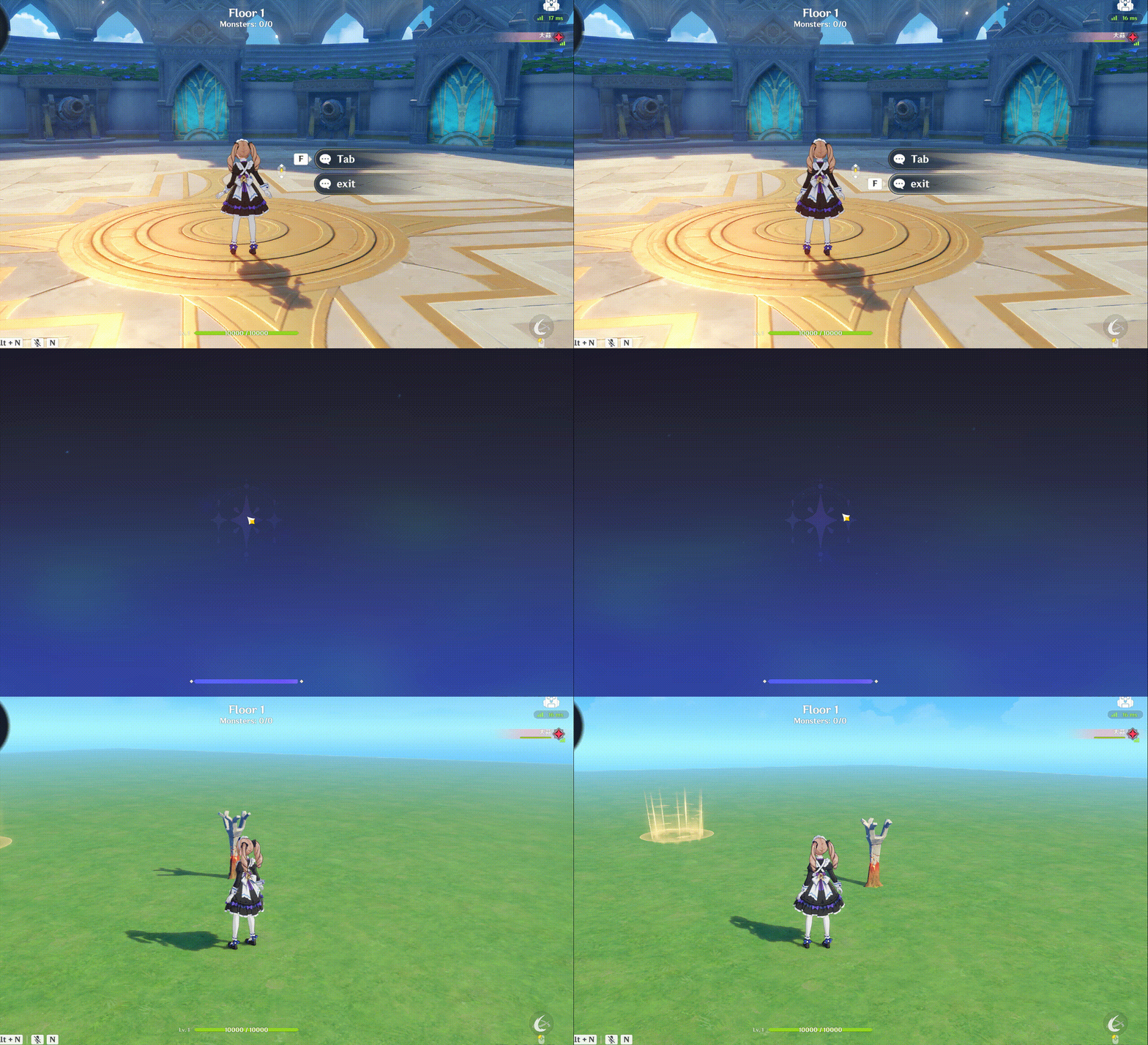
4.1.2 Controlling UI Through State
You may have noticed that when we modify a Custom Variable, the last parameter is Trigger Event.
When this option is enabled, an event will be triggered whenever the value changes.
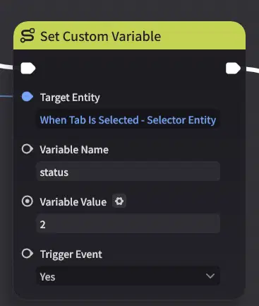
So, our starting point is when the status value changes—in other words, when the player’s state is updated.
Create a new Node Graph and bind it to the player character.
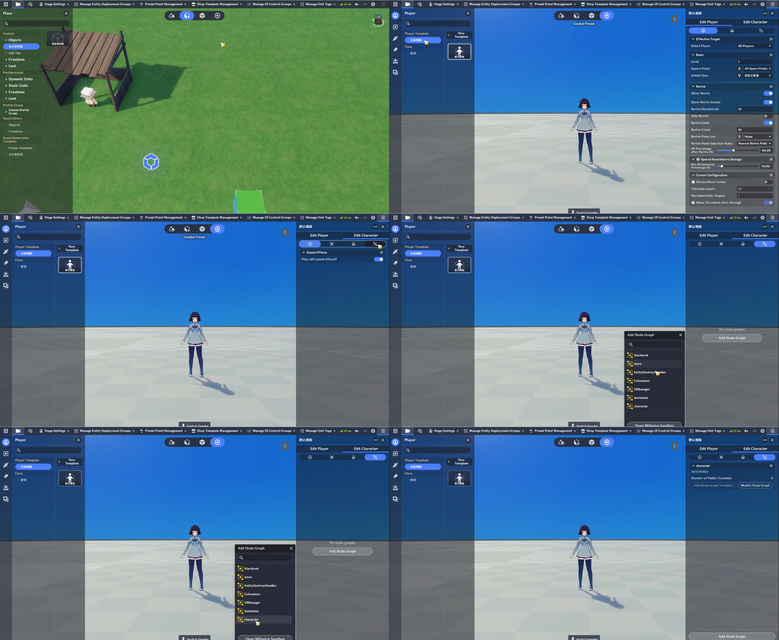
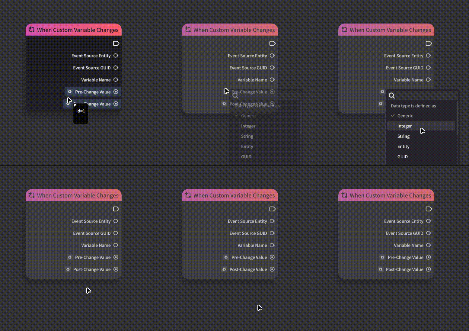
Now, let’s start editing the Node Graph.
When using this node, make sure to click the gear icon and set its type to match the corresponding variable type. Otherwise, the event will not trigger correctly.
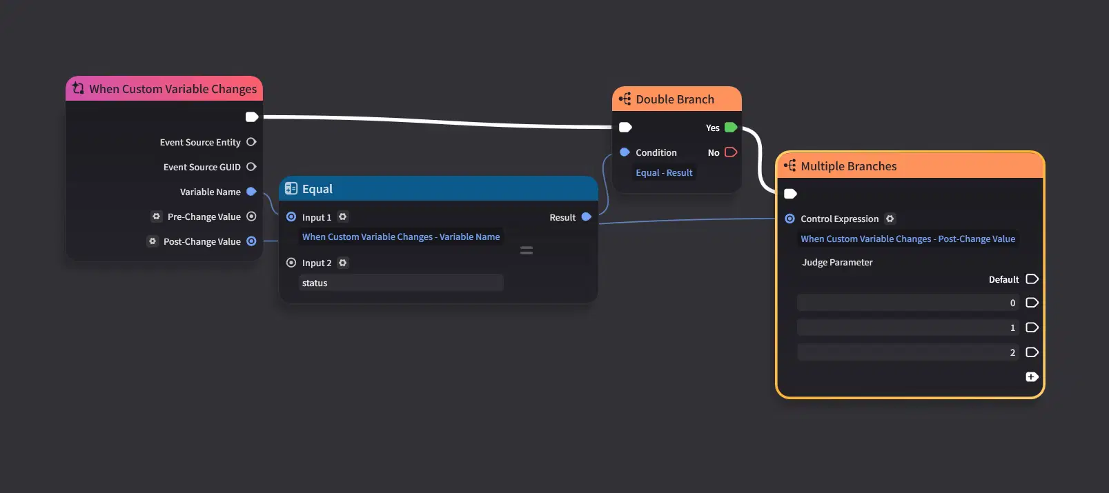
Handle each state separately with its own corresponding logic.
Before making these changes, there’s one thing worth mentioning:
For dynamic UI elements like these, we shouldn’t keep them permanently placed on the screen, as that is not ideal for performance.
A better approach is to save them as templates, create them when needed, and destroy them when they are no longer required.
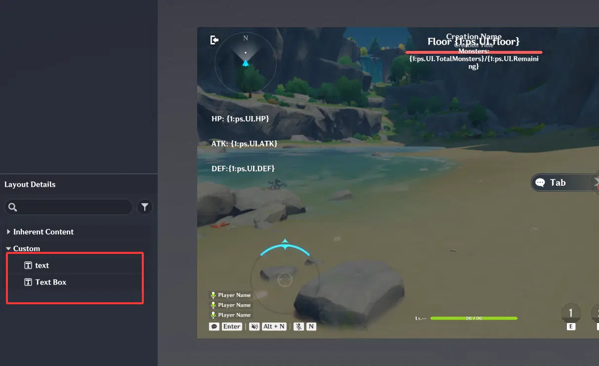
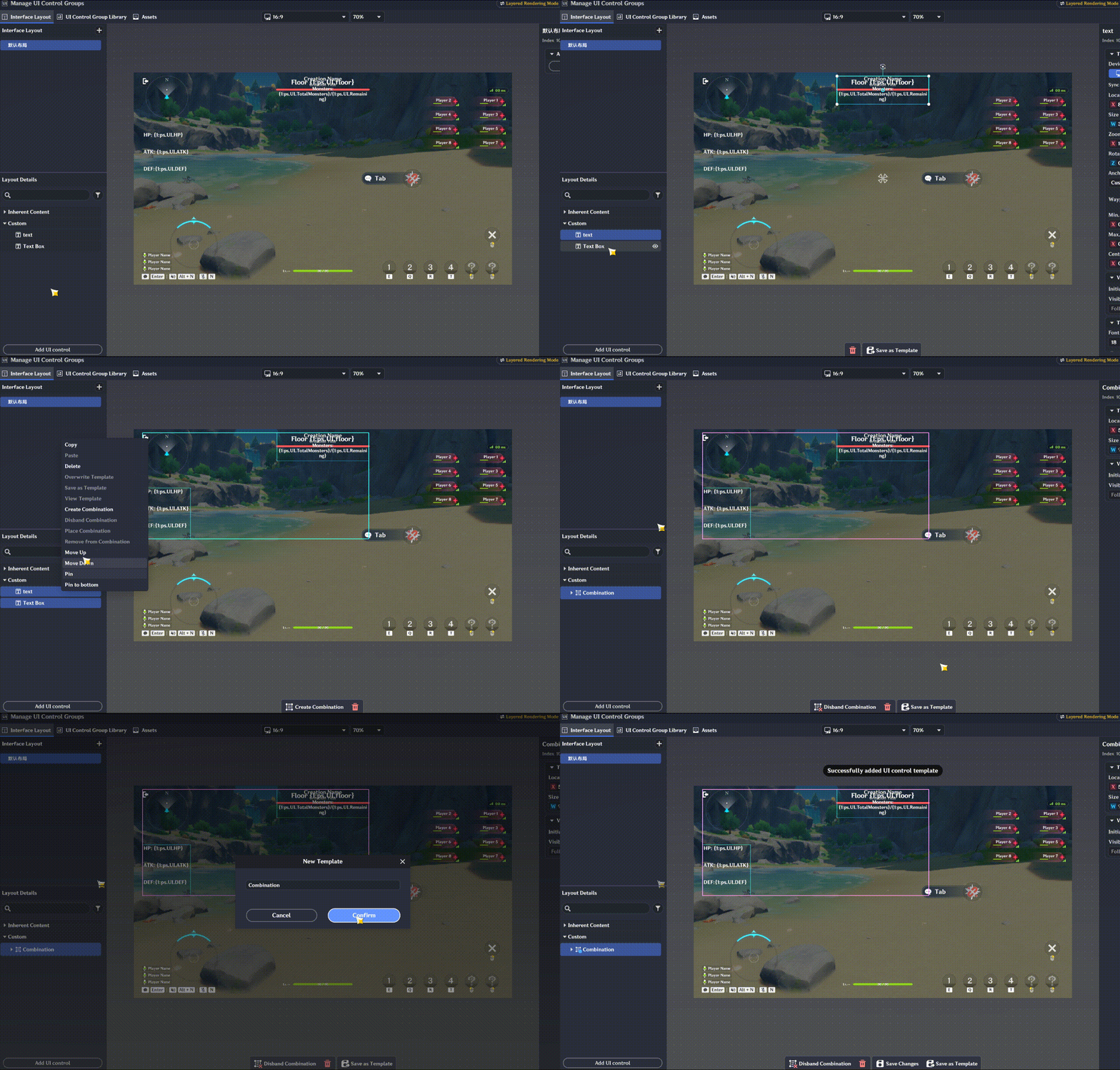
Since these two UI elements always appear and disappear together in our scene, we’ll group them together and save them as a single template.
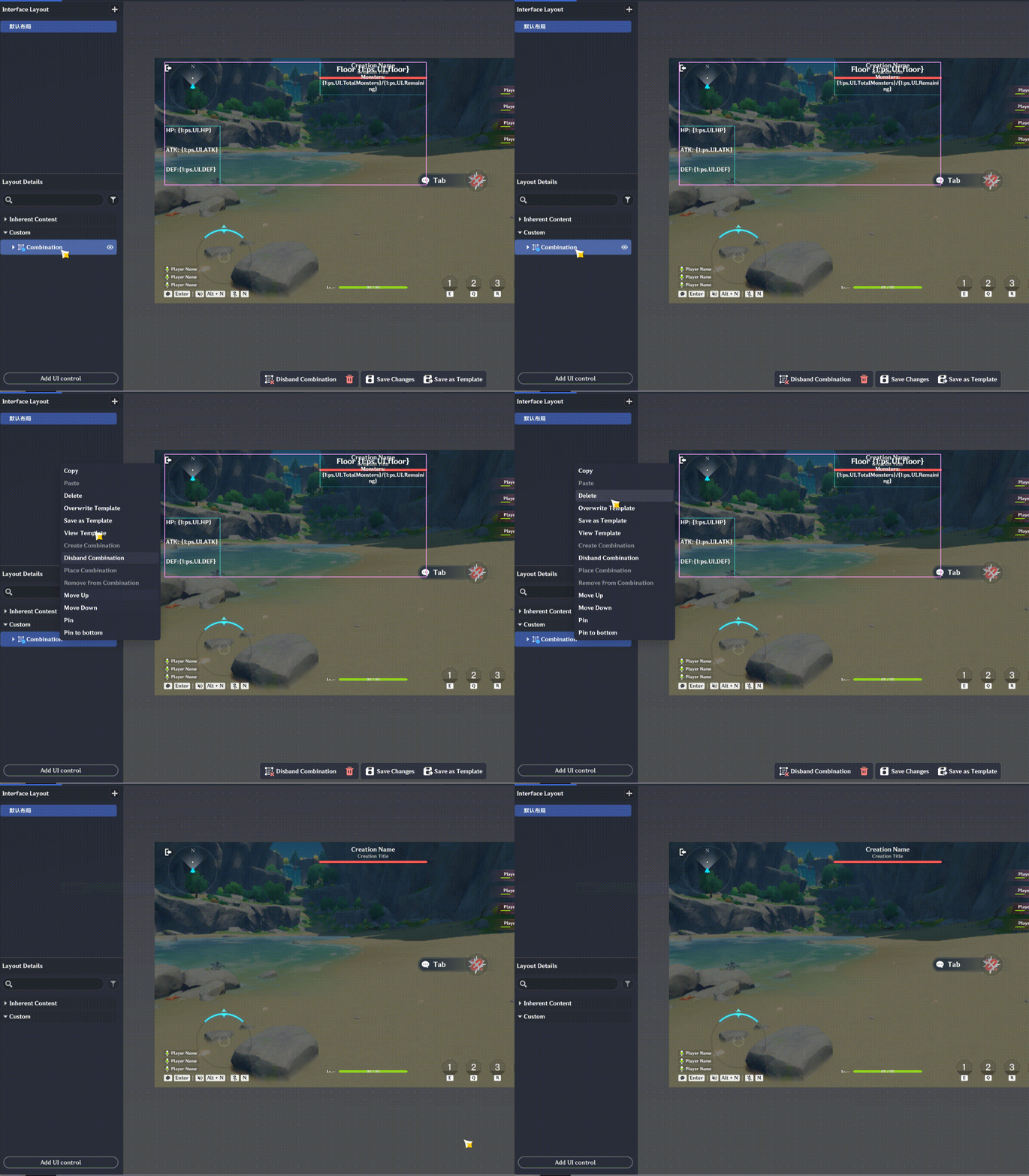
Once the template has been saved, you can remove these UI elements from the default layout.
Return to the Node Graph.
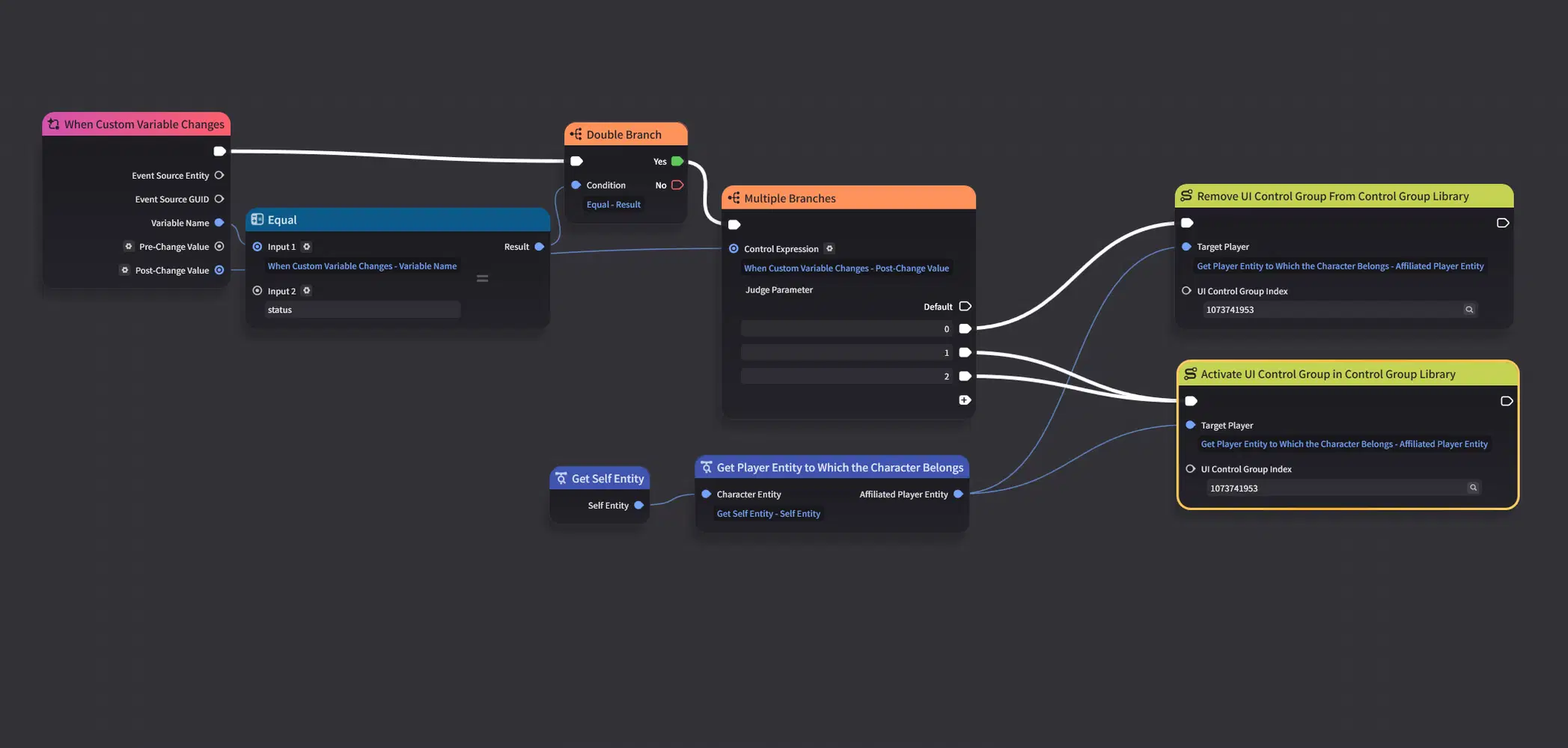
Let’s clarify the logic first:
0 → Hide the Floor and Stats UI
1 / 2 → Show the Floor and Stats UI
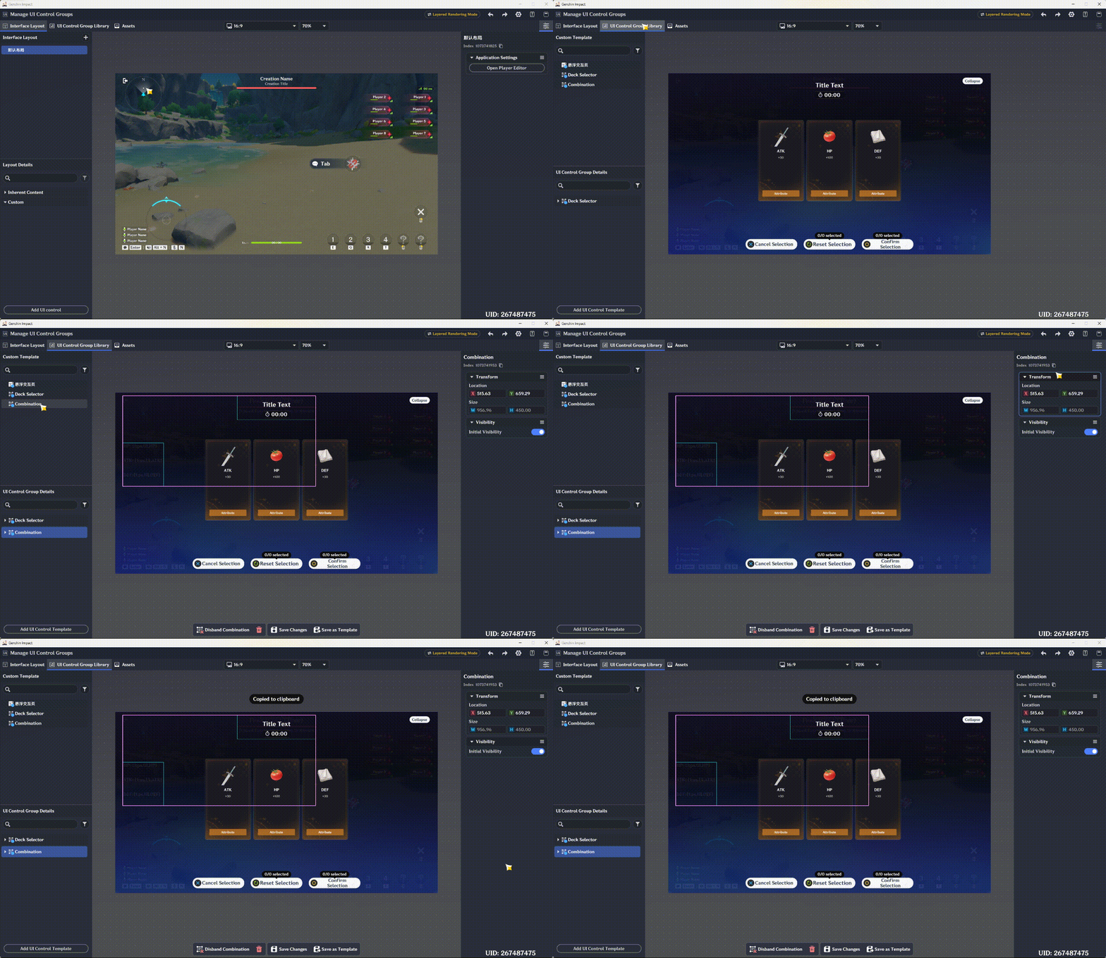
First, copy the template index.
Modify the Node Graph to show and hide the UI.
Since this is a player character Node Graph, we first need to get the Player Entity from the player character.
One more thing to add:
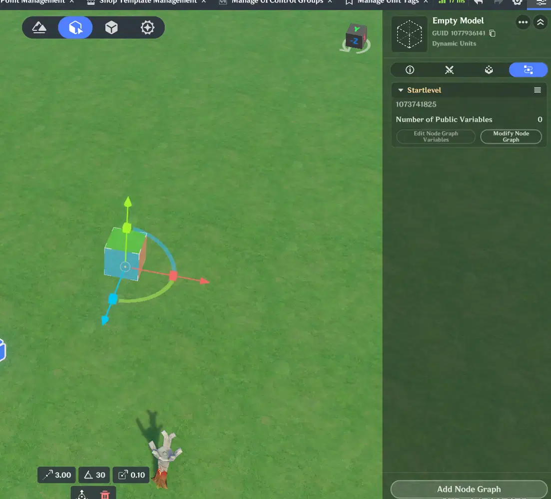
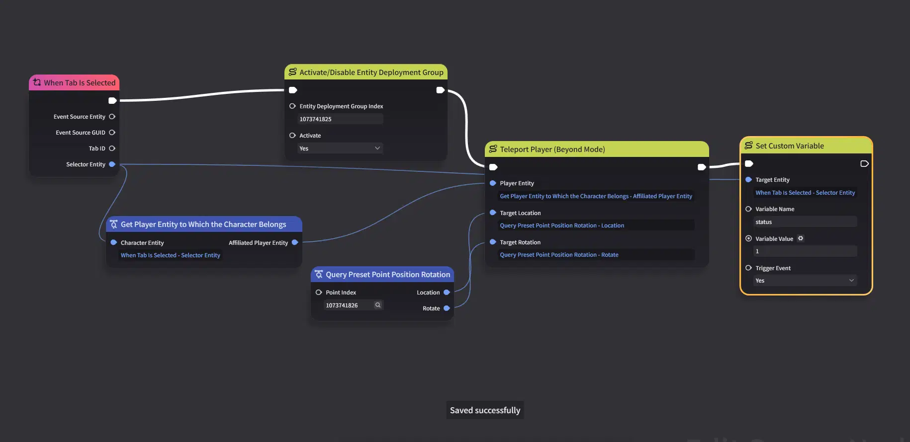
In the Node Graph that handles entering the Stage, we also need to update the player’s state so that the UI can respond correctly.
When the player enters the Stage, set status to 1.
Let’s test it again!
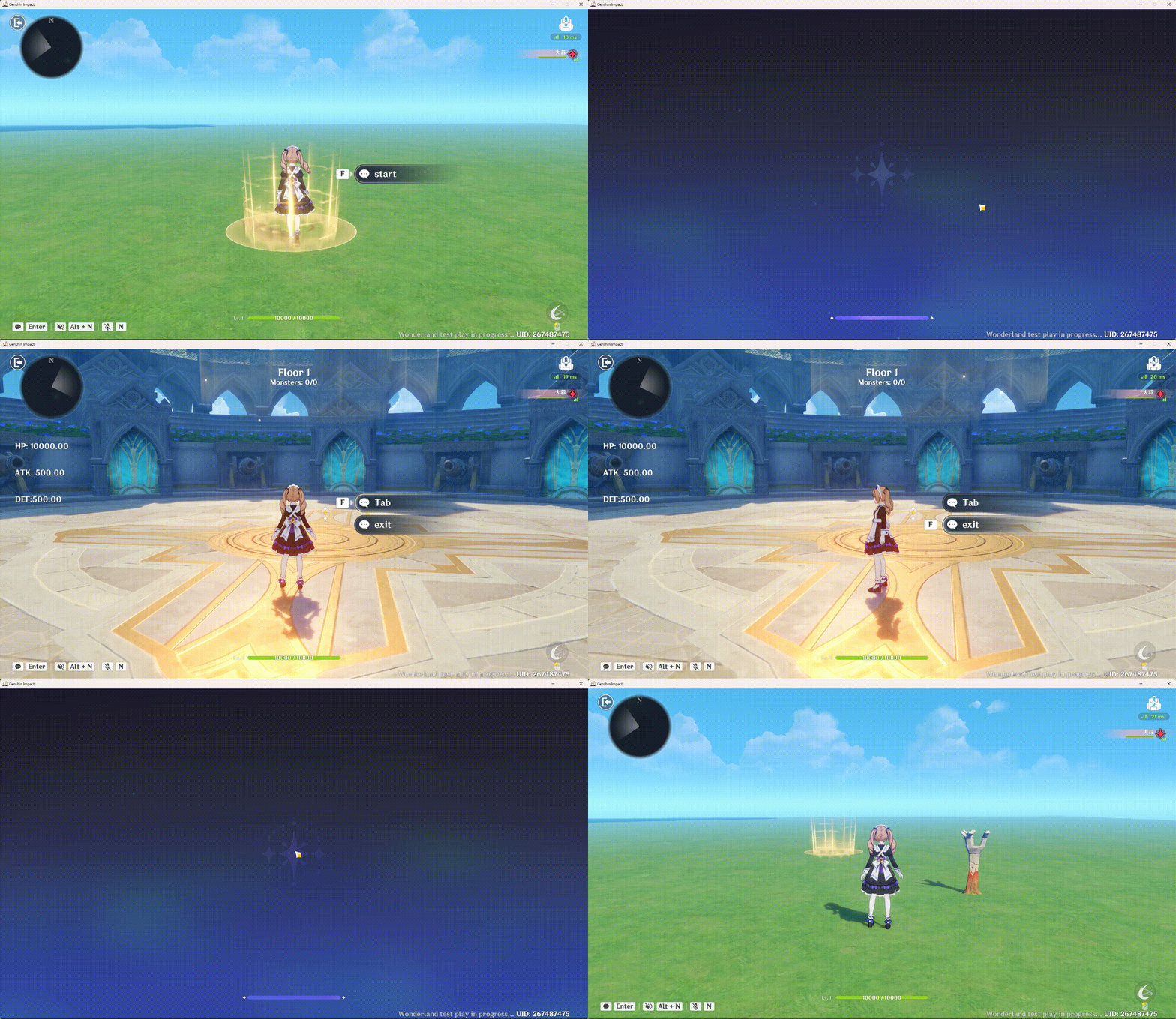
As you can see, the UI now shows and hides correctly based on the states we configured.
4.2 State Tracking and Cleanup
To remove States properly, we first need to know which States have actually been applied, rather than blindly clearing everything.
Of course, there is another way: all States are cleared when the player character dies. However, that would result in a poor experience, since players are unlikely to appreciate being defeated for no apparent reason.
4.2.1 State Tracking
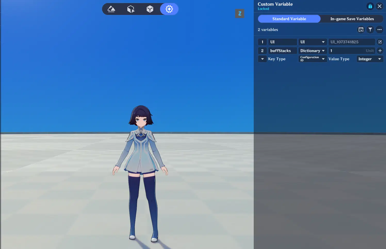
Tracking States is very simple. Just add a Dictionary to the Player Variables and use each State as the key.
Return to the arena Node Graph.
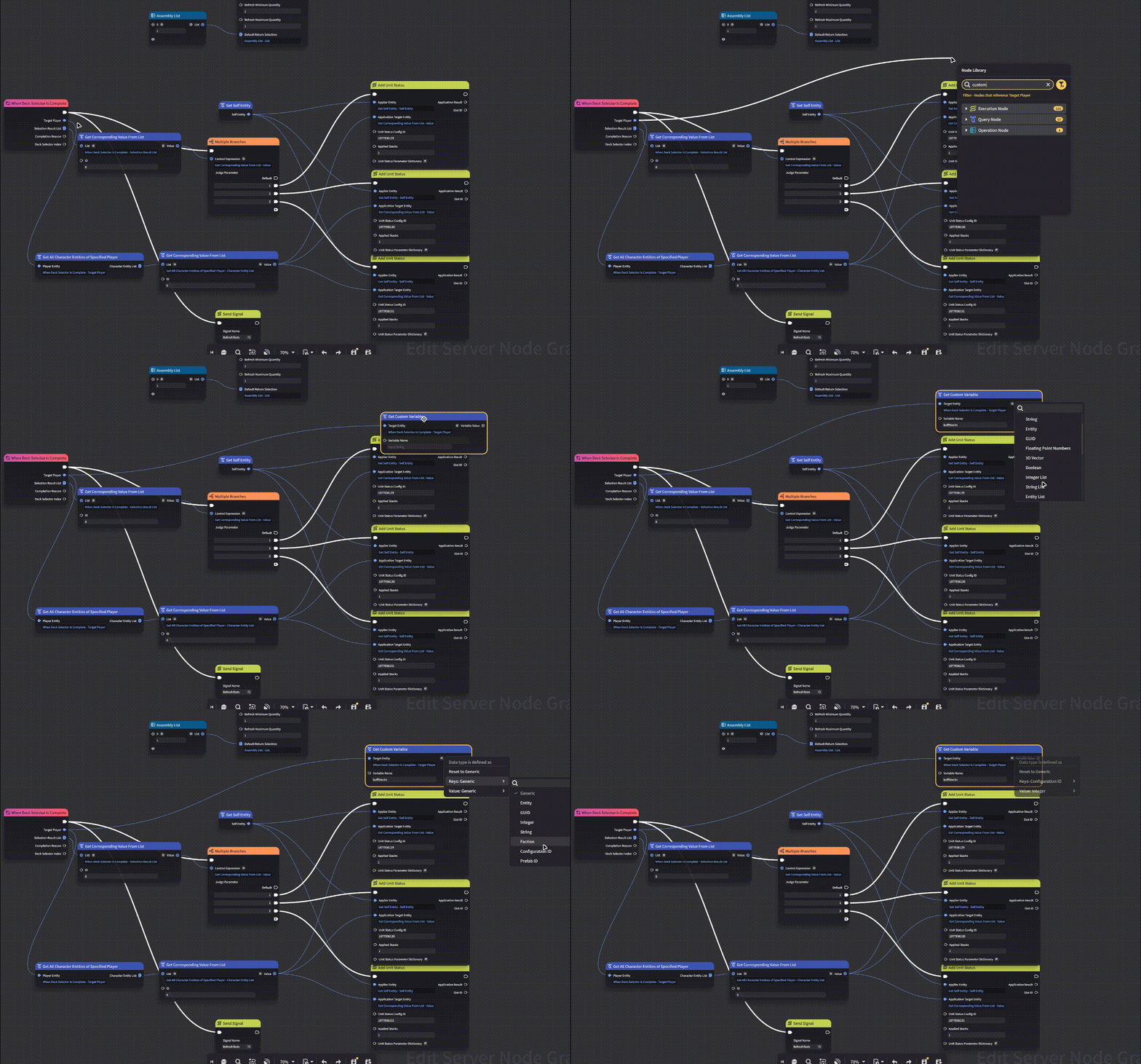
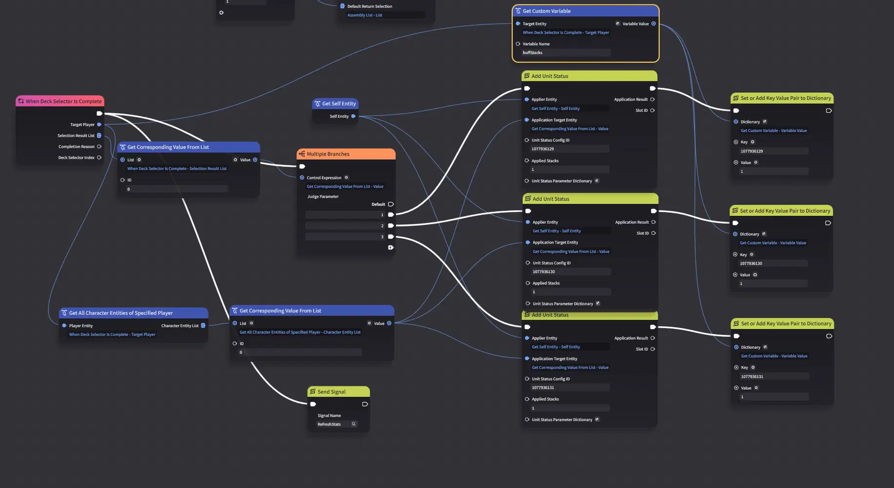
After applying a State, add it to the Dictionary as well.
When using a Dictionary as a Custom Variable, make sure to configure the key and value types in advance.
4.2.2 State Cleanup
Get the Dictionary we stored earlier, iterate through its keys, and remove each corresponding State one by one.
For buff-type effects, some creators may choose to use a shared State to handle multiple values—for example, using the same State for both +5 ATK and +10 ATK. We won’t use that approach here, because it requires additional logic to manage and calculate the actual buff values, which can also make calculation errors more likely.
Return to the Node Graph, locate the logic for Tab Component 2, and continue building the cleanup logic there.
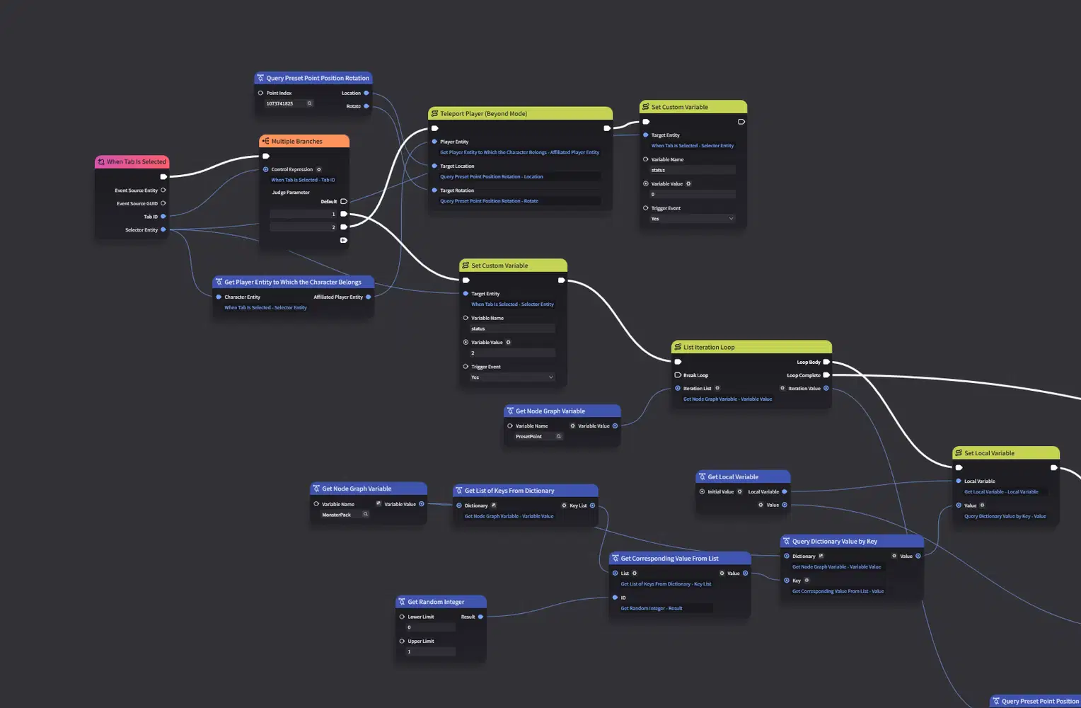
Get the list of keys from the variable, then iterate through the list and remove each State one by one.
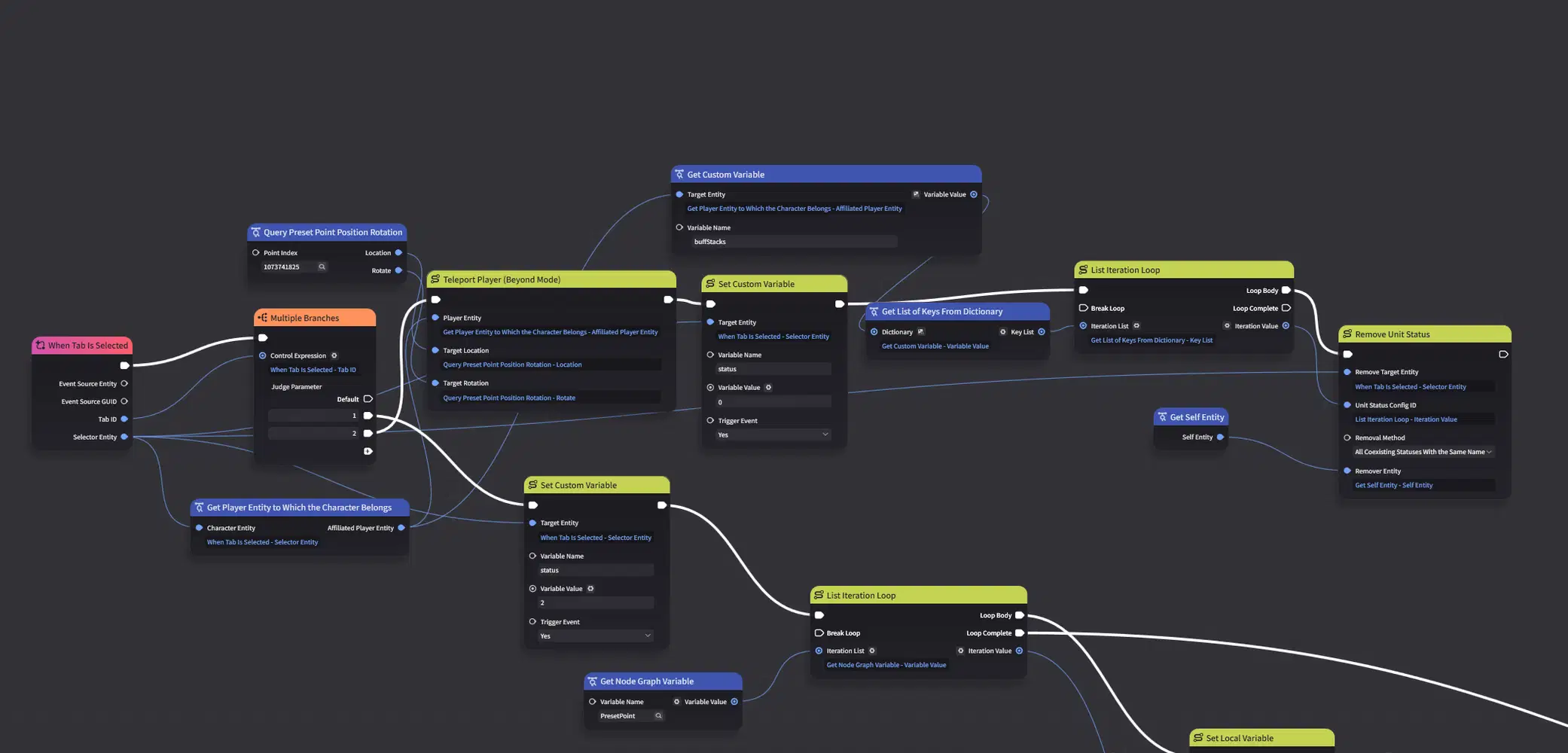
Once the cleanup is complete, don’t forget to refresh the UI.
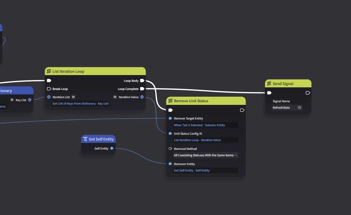
Now, let’s continue testing. Clear one Floor, return to the home area, then enter the Stage again.
Check whether the stats have returned to their original values to confirm that the cleanup worked correctly.
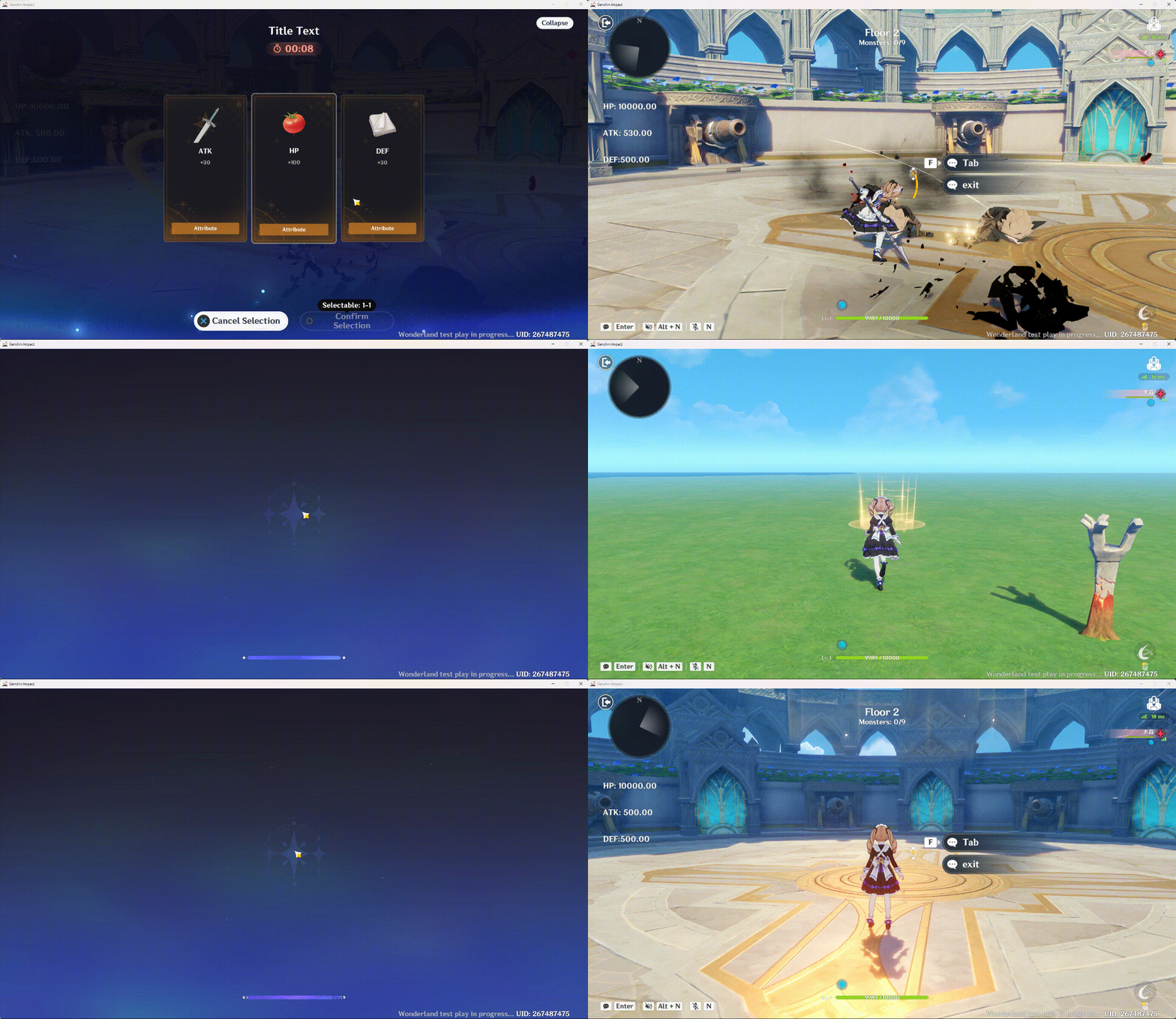
As you can see, the States were successfully cleared!
More updates coming soon~
This is getting too long, so the next chapters will be posted in a separate thread.